14328
D0000035039
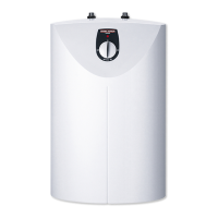
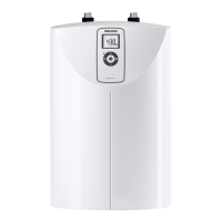
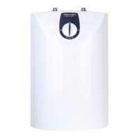
SNU 5 SL 1 kW SNU 5 SLi
c01 Cold water Inlet Male thread G 3/8 A G 3/8 A
c06 DHW outlet Male thread G 3/8 A G 3/8 A
15.2 Wiring diagram
1/N/PE ~ 220 - 240V
LN
85�02�06�0001
15.3 Heat-up diagram
The heat-up period depends on the degree of scaling and residual
heat. For the heat-up time for a cold water supply of 10 °C and a
maximum temperature setting, see the diagram.
35 40 45 50 55 60 65 70 75 80 85
0
5
10
15
20
25
30
1
2
84�02�02�0044
x Temperature settings in °C
y Duration in min
1 1kW appliance
2 2kW appliance
15.4 Country-specific approvals and certifications
The test symbols can be seen on the type plate.
15.5 Extreme operating and fault conditions
In the case of faults, a peak temperature up to 100 °C may briefly
occur in the system.
 Loading...

