INSTALLATION
Installation
12 | WPL E | WPL cool www.stiebel-eltron.com
26_03_01_0958_
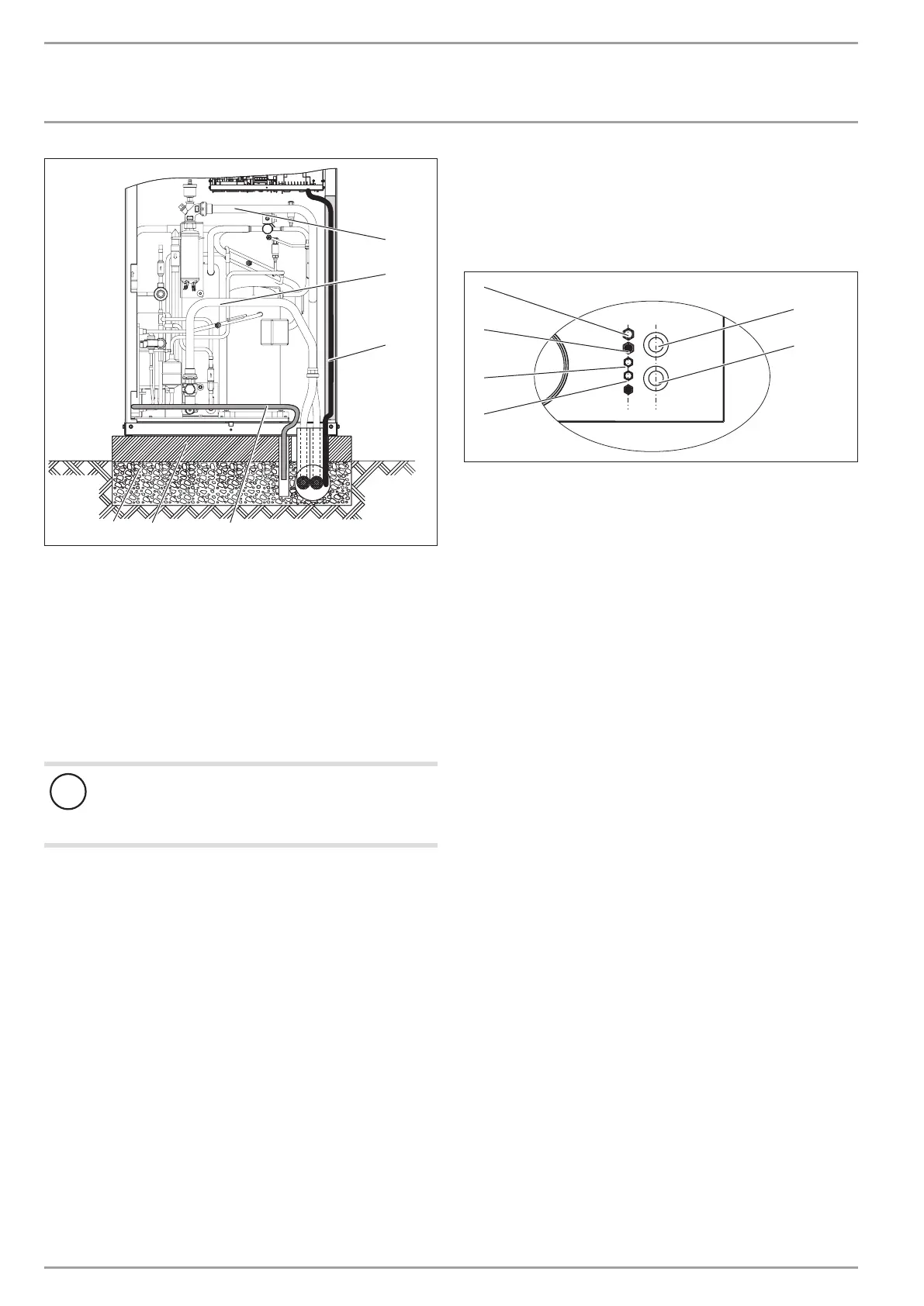
1
3
2
6
5
4
1 Pipe bend for heating circuit flow
2 Pipe bend for heating circuit return
3 Cable duct
4 Condensate drain hose
5 Concrete foundation
6 Coarse gravel back filling
Fit the pipe bends "heating circuit flow" and "heating circuit
return".
Route the supply pipes/cables from below through the knock-
out in the bottom and into the appliance.
Route the electrical cables in a cable duct.
!
Material losses
Rodents may get into the appliance through the knock-
out aperture.
Close off the knock-out aperture.
10.2.2 Indoor installation
Position the standard appliance on the prepared substrate.
Pay attention to the air discharge direction.
Place the casing cover on the appliance and secure with two
screws.
5
4
3
6
26_03_01_0170
2
1
1 "Heating flow" connection
2 "Heating return" connection
3 BUS cable
4 Control cable
5 Electric emergency/booster heater power cable
6 Appliance power cable
In the cover, cut out the pipe outlets for the "heating flow"
and "heating return" connections.
Route the pressure hoses from above through the cover and
into the appliance.
Route the electrical cables from above through the cable en-
tries and into the appliance.
With the indoor installation, rotate the connector for the "heating
flow" connection through approx.145°.
0

 Loading...


