INSTALLATION
Fitting casing components
18 | WPL E | WPL cool www.stiebel-eltron.com
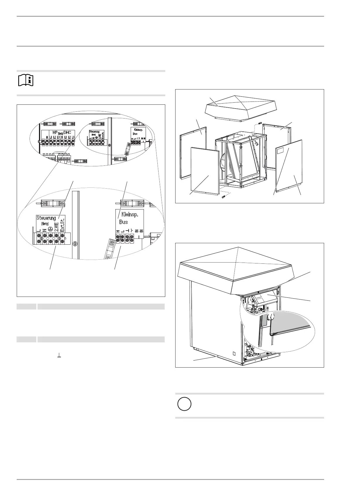
Connections X4, X2: Control unit and low voltage
Note
Provide common fuses/MCBs for the control cable of the
appliance and the heat pump manager.
26_03_01_0949_
1
2
X2
X4
1 Control unit ("Steuerung")
Power supply: L, N, PE
Control inputs:
Heat source 2 (2. WE)
External control, e.g. standalone operation (Ext.St.)
2 Low voltage (LV)
BUS High H
BUS Low L
BUS earth
BUS " + " (not required)
12. Fitting casing components
12.1 Outdoor installation
2
1
3
1
5
4
26_03_01_0929_
1 Side panel
2 Cover
3 Front panel
4 Type plate
5 Back panel
26_03_01_1738
1
2
3
1 Bevelled edge
2 Control panel
3 Screw
!
Material losses
The cover protects the PCB from water ingress.
Install the cover with the drip edge above the PCB.
Secure the cover with two screws.
Hook the side panels, front panel and back panel into the
hooks on the standard appliance. Secure the casing sections
at the bottom with one screw each.
Affix the type plate supplied in a highly visible position on
one of the appliance casing panels.
l.
0

 Loading...


