WORKSHOP MANUAL
EDITION
PAGE
72 /
124
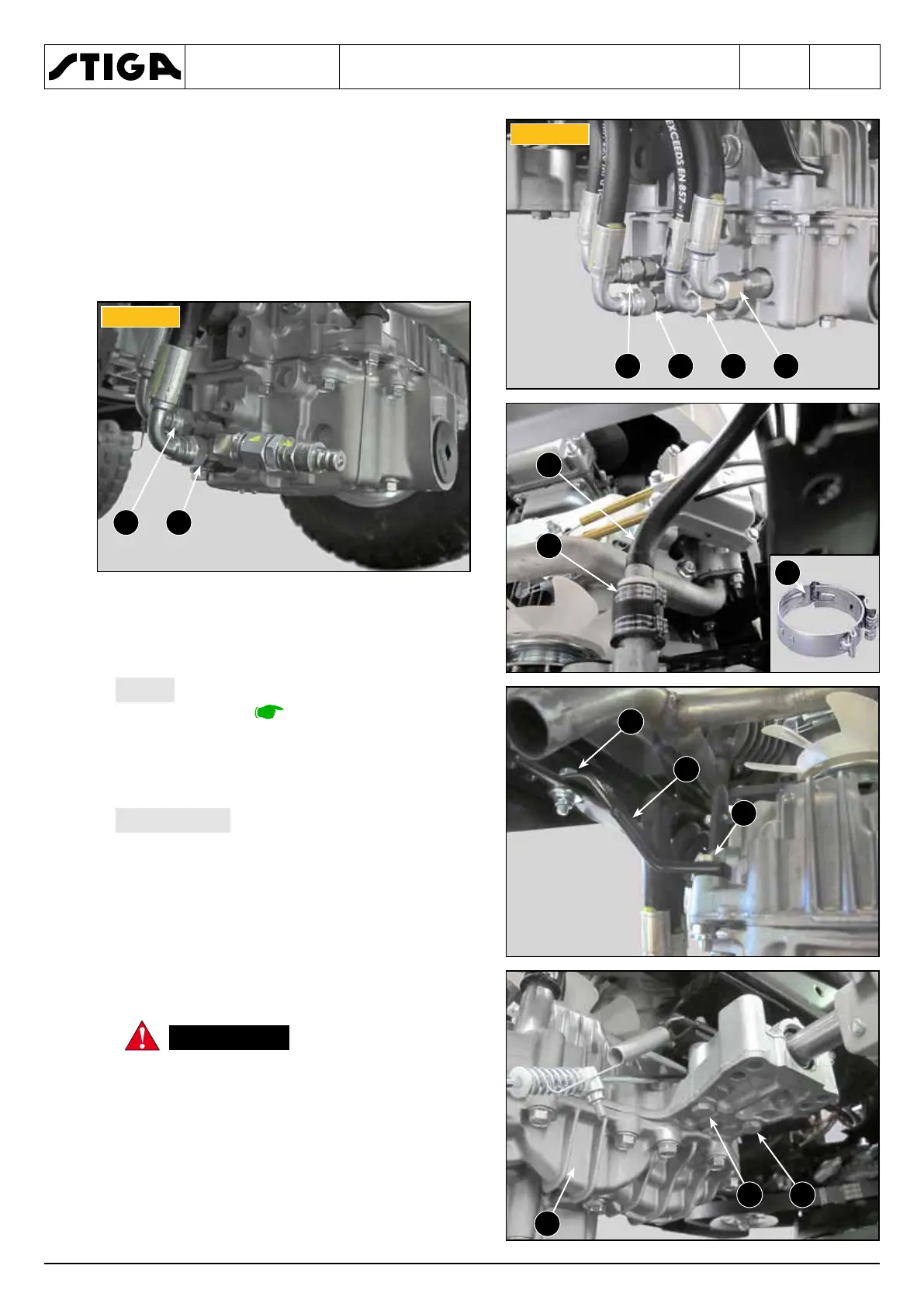
8. Disconnect all hydraulic connections:
– unscrew the fittings (18 - 19 - 20 - 21) marking
them appropriately so as not to make mistakes
during assembly;
18 = Hydraulic steering valve return pipe
19 = Hydraulic steering valve delivery pipe
20 = Front transmission return pipe
21 = Front transmission delivery pipe
for all hydraulic connections, see the
overall diagram.
– remove the upper clamp (22) and disconnect
the pipe fitting (23) connecting with the oil tank.
The clamp (22) is of the “CLIC”
type as it meets the safety criteria required for
this application. Therefore, in case of replace-
ment, it is necessary to use an original spare
part and NOT a common screw clamp.
9. Loosen the screw (24) and unscrew the screw
(25) of the reaction bracket (26).
The unit is secured
to the frame by four screws. Loosen the
screws carefully, adequately supporting
the transmission unit so as not to cause
it to fall.
10. Unscrew the four screws (27) and the trans-
mission unit (28) can be removed from the
machine
▶▶
▶▶
 Loading...