WORKSHOP MANUAL
T...102/122 - TC...102/122
Map of functional units
To make this test it is necessary to have:
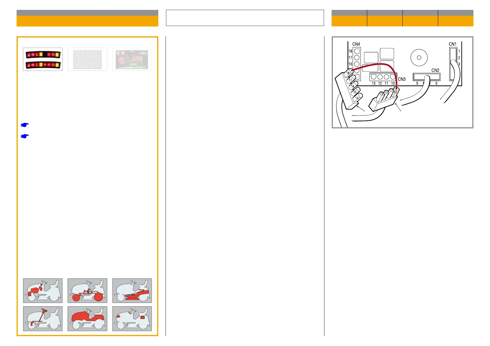
– Connectors CN1 and CN2 disconnected (1)
– The key in the «ON» position
When bridging between terminals 10 (CN3) and 18
(CN4) of the cabling connectors (1), a click must be
heard from the moving part of the clutch, due to exci-
tation of the electric winding.
If this does not occur, check the wiring and the o -
peration of the control push-button and ensure that
the card is operating correctly.
The clutch must be replaced if engagement does not
take place after these checks.
ELECTROMAGNETIC CLUTCH OPERATION
CHECK
Validity
General informations
Related topics
[
7.3] Safety microswitches operation check
[
7.8] Electronic card operation check
CHAPTER REVISION FROM ... PAGE
7.7 0 2018 1 of 1

 Loading...