WORKSHOP MANUAL
T...102/122 - TC...102/122
Map of functional units
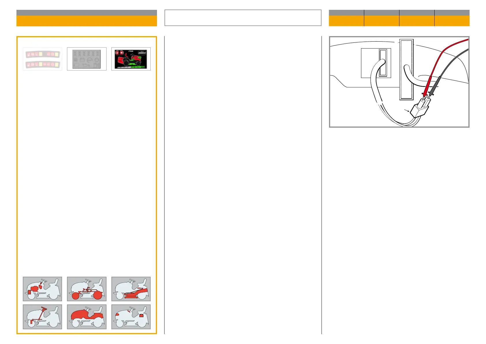
The following conditions must be ensured to make
this check:
– key set to «ON»,
– connector CN2 connected,
– operator seated,
– blades disengaged.
The check is made with the tester in Voltmeter mo de
(0 ÷ 20 Volts DC) and with the probes on the connec-
tor (2) output cabling terminals.
When one of the two keys is pressed the instrument
reading shows the battery voltage (positive or nega-
tive); this value must never fall below 11.5 Volts.
If no power is detected it means that the 15 A fuse has
blown or that there is a fault in the actuator board.
1
2
3
4
1 11
2 12
3 13
4 14
5 15
6 16
7 17
8 18
9 19
10 20
CN2
CN1
Validity
General informations
Related topics
---
CHECKING THE OPERATION OF THE BAG
EMPTYING CONTROL
CHAPTER REVISION FROM ... PAGE
7.18 0 2018 1 of 1

 Loading...