WORKSHOP MANUAL
T...102/122 - TC...102/122
Map of functional units
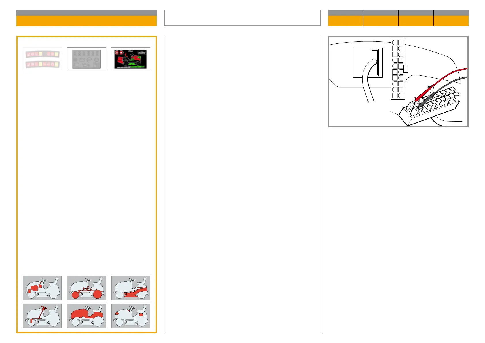
This check is made with the tester operating as a
Voltmeter (Volts DC 0 ÷ 20), with the black ferrule on
terminal 1 and the red one on terminal 11of the con-
nector (1) of the wiring.
– The key in the «ON» position
The reading shows the battery voltage, which should
never go below 11 Volts.
1
2
3
4
12
13
14
15
16
17
18
19
20
11
3
4
5
6
7
8
9
10
1
2
CN2
CN1
1 11
2 12
3 13
4 14
5 15
6 16
7 17
8 18
9 19
10 20
Validity
General informations
Related topics
---
TERMINAL BOARD SUPPLY CHECK
CHAPTER REVISION FROM ... PAGE
7.14 0 2018 1 of 1

 Loading...