EN - 4
3.3.
Contact an authorised service centre to connect
the battery.
Before rst use, fully charge the battery
See 6.4 for battery charging procedures.
3.4.
See gure 4.
NOTE To facilitate installation of the seat, apply a drop of oil
to the four screws before screwing them into the seat.
The seat will be damaged if the screws are
tightened to a torque exceeding 24 Nm.
3.5.
See gure 5.
3.6.
See gure 6.E.
Pass the mower cable with seated operator in the guide of
the lifting pulley.
After attaching an attachment to the mower with the driver
seated, place the lifting pulley in the appropriate seat on the
attachment and secure it by turning its knob.
3.7.
SUPPORTS
See gure 10.
NOTE The quick-release supports and the relative instruc-
tions are supplied in a separate package in the packaging of
the machine.
3.8.
For assembly and disassembly operations, refer to the
instructions supplied with the manual for the cutting means
assembly.
3.9.
The following assembly instructions are intended as a
supplement to the instructions provided with the attachment
manual.
1. Ensure that the quick-release supports are installed.
2. Place the attachment brackets on the quick release
supports in the open position.
3. Wrap the belt around the machine's pulleys and tension
it (Front power sweeper only).
4. Fit the belt guard housing and ensure that it is in the
correct position (Front power sweeper only).
5. Connect the lifting pulley to the attachment, inserting it
into the appropriate seat and secure it using the knob.
6. Close the quick release supports in the working position.
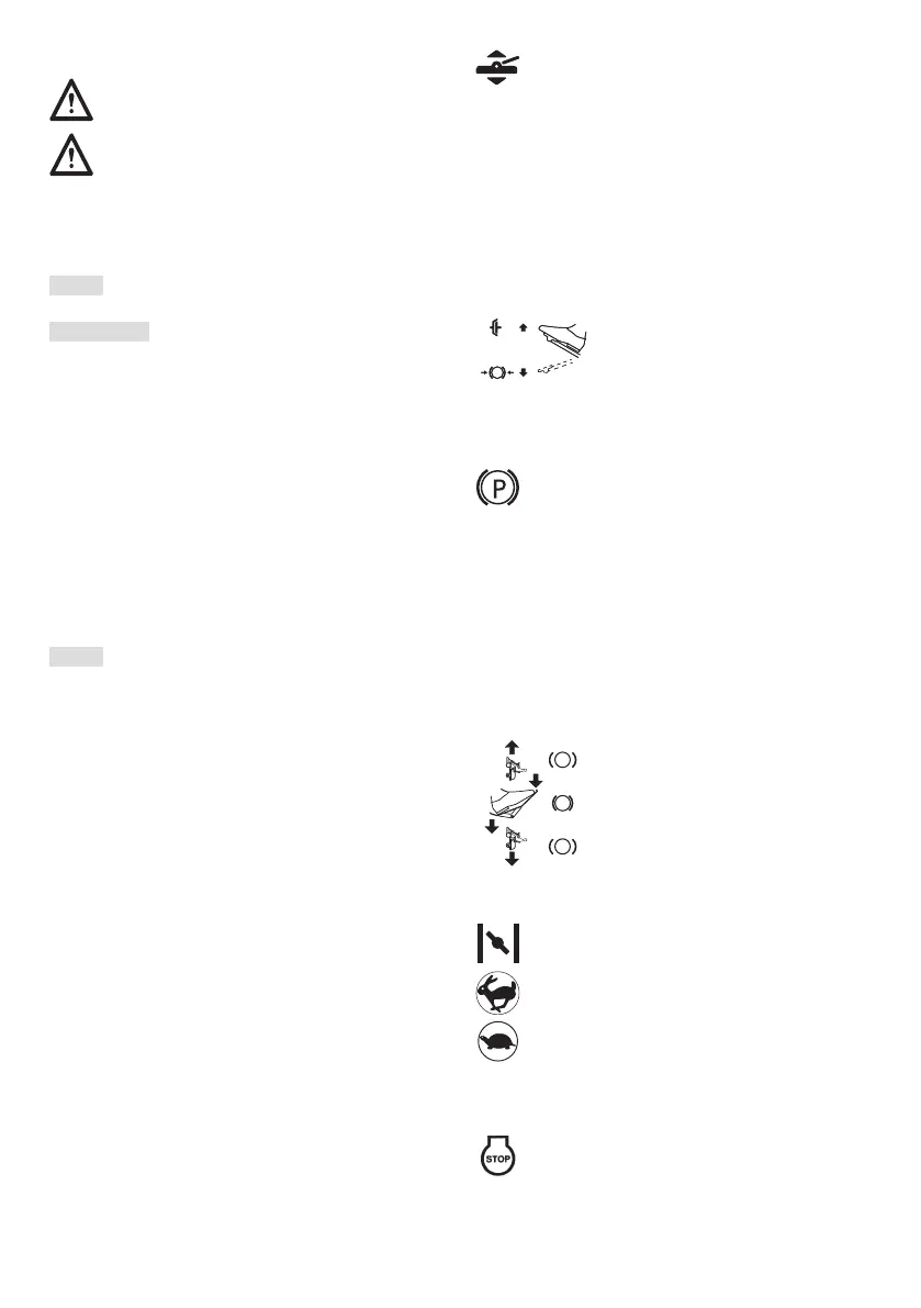
4. CONTROLS
•
It controls the lifting system and is used to bring
the accessories from the working position to the
transport position.
Transport position:
Depress the pedal fully and remove the foot, the pedal
remains depressed.
Work position:
1. Depress the pedal fully.
2. Move the stop (6:B) to the left.
3. Release the pedal.
•
Released: the parking
brake is not activated.
Fully pressed: forward drive is
disengaged. The parking brake is
fully activated but not locked.
•
Locks the parking brake pedal in the fully
depressed position. This function is used
to secure the machine on slopes, during
transport, etc., when the engine is stopped.
Locking:
1. Depress the pedal fully (6:D).
2. Move the stop (6:A) to the left.
3. Release the pedal (6:D).
4. Release the stop (6:A).
Unlocking:
Press and release the pedal (6:D).
•
By pressing the pedal forwards, the
machine advances.
When there is no load on the pedal the
machine is stopped.
By pressing the pedal backwards, the
machine moves in reverse gear.
By reducing pressure on the pedal the
machine brakes.
•
Air.
Full on.
Idle.
•
The ignition switch is used to start and stop the engine.
Stop position.