STIHL 064, 066 54
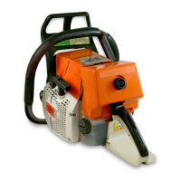
5.1.6.1 Ignition Timing 5.1.6.2 Removing and Installing
Top: Top:
1 = Wire retainer Pulling unscrewed ignition lead
2 = Wire to LED (066 only) out of ignition module
3 = Short circuit wire
Bottom:
Bottom: Removing wire retainer from
Digital ignition module mounting screws ignition module
Ignition timing on the transistor - controlled
magneto ignition systems is fixed at 2.6 -
3.4 mm (0.10" - 0.13") B.T.D.C. at 8,000
rpm on the 064 and 2.9 - 3.9 mm (0.11" -
0.15") B.T.D.C. at 8,000 rpm on the 066. It
is not adjustable. However, in view of the
permissible tolerances in the electronic
circuit, it may vary between 2.5 - 3.5 mm
(0.09" - 0.14") B.T.D.C. at 8,000 rpm.
Since there is no mechanical wear in these
systems, ignition timing cannot get out of
adjustment. However, an internal fault in the
circuit can alter the switching point in such a
way that a spark test will still show the
system to be in order although timing is
outside the permissible tolerance. This will
impair engine starting and running behavior.
- Remove fan housing - see 5.1.5. - Unscrew the ignition lead from
the contact pin. To do this, rotate
- Disconnect short circuit wire and the ignition module and pull the
wire to LED (on 066) from tags lead out of the high voltage out
on ignition module and take them put.
out of the retainer.
- If necessary, remove the wire
- Remove the ignition module retainer from the module.
mounting screws.
Note: The digital ignition module
can be installed in saws from ma-
chine number X 18 761 250, or
saws with a new crankcase, which
have a third mounting boss for the
yoke of the digital ignition module.