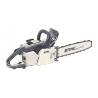
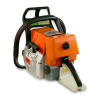
EasyManua.ls Logo

Stihl 034 Series

Stihl 034 Series
72 pages
To Next Page IconTo Next Page
Loading...
1034, 036, 036 QS
© 2001 Andreas Stihl AG & Co., Waiblingen
Contents
1 Introduction 2
2 Safety Precautions 3
3 Specifications 4
3.1 Engine 4
3.2 Fuel System 4
3.3 Ignition System 5
3.4 Cutting Attachment 5
3.5 Tightening Torques 6
3.6 Special Accessories 7
3.6.1 For User 7
3.6.2 For Service 7
4 Clutch, Chain Drive,
Chain Brake and
Chain Tensioner 8
4.1 Clutch Drum and Chain
Sprocket 8
4.2 Replacing the
Chain Catcher 9
4.3 Clutch 9
4.4 Chain Brake (034, 036) 10
4.4.1 Removing 10
4.4.2 Installing 11
4.5 Chain Brake (036 QS) 12
4.5.1 Removing 12
4.5.2 Installing 14
4.5.3 Checking Play 15
4.5.4 Adjusting Play 16
4.5.5 Checking Operation of
Chain Brake 17
4.6 Chain Tensioner 17
4.7 Bar Mounting Studs 18
5Engine 19
5.1 Removing and
Installing Muffler 19
5.2 Exposing the Cylinder 20
5.3 Cylinder and Piston 20
5.3.1 Removing 20
5.3.2 Installing 21
5.4 Piston Rings 24
5.5 Crankcase 24
5.5.1 Removing the
Crankshaft 24
5.5.2 Installing the
Crankshaft 26
5.6 Crankcase Leakage
Test 31
5.6.1 Preparations 31
5.6.2 Pressure Test 32
5.6.3 Vacuum Test 33
5.7 Replacing the Oil
Seals 33
6 Ignition System 34
6.1 Ignition Lead/
Spark Plug Boot 34
6.2 Short Circuit Wire/
Ground Wire 35
6.3 STOP Contact 37
6.4 Flywheel 38
6.4.1 Removing 38
6.4.2 Installing 38
6.5 Ignition Module 39
6.5.1 Removing and
Installing 39
6.5.2 Ignition Timing 40
7 Rewind Starter 40
7.1 Routine
Maintenance 40
7.2 Rope Rotor, Pawls,
Starter Rope,
Rope Guide Bush 40
7.3 Rewind Spring 41
7.3.1 Replacing the Rewind
Spring (034) 41
7.3.2 Replacing the Rewind
Spring (036, 036 QS) 41
7.4 Tensioning the Rewind
Spring 42
8 AV Handle System 42
8.1 Repair 42
9Master Control 43
9.1 Construction and
Function 43
9.2 Throttle Trigger/Interlock
Lever (034, 036) 44
9.3 Throttle Trigger/Interlock
Lever/Switch Lever
(036 QS) 45
9.4 Switch Shaft 46
10 Electric Handle Heating
System (034, 036) 47
10.1 Troubleshooting 47
10.1.1 Troubleshooting Chart 49
10.1.2 Test Connections and
Test Values 50
10.2 Heater Switch 51
10.3 Heating Element
in Rear Handle 51
10.4 Heating Element in
Front Handle 53
10.5 Generator 54
10.5.1 Removing 54
10.5.2 Installing 55
11 Chain Lubrication 55
11.1 Pickup Body 55
11.2 Suction Hose 56
11.3 Vent Valve 56
11.4 Removing and
Installing the Oil Pump 57
11.5 Servicing the Oil Pump 58
12 Fuel System 59
12.1 Air Filter 59
12.2 Leakage Testing the
Carburetor 60
12.3 Removing and Installing
the Carburetor 61
12.4 Servicing the
Carburetor 62
12.5 Adjusting the
Carburetor 66
12.6 Tank Vent 67
12.7 Fuel Filter and Fuel
Hose 68
12.8 Tank Housing 69
12.8.1 Removing and
Installing 69
13 Special Servicing
Tools and Aids 71
13.1 Special Servicing
Tools 71
13.2 Servicing Aids 72

Table of Contents

Questions and Answers:

Stihl 034 Series Specifications

General IconGeneral
BrandStihl
Model034 Series
CategoryChainsaw
LanguageEnglish

Summary

1 Introduction

2 Safety Precautions

3 Specifications

3.1 Engine

Detailed specifications for the STIHL engine, including displacement, bore, and stroke.

3.2 Fuel System

Specifies settings and capacity for the carburetor, fuel mixture, and air filter.

4 Clutch, Chain Drive, Chain Brake and Chain Tensioner

4.1 Clutch Drum and Chain Sprocket

Procedure for removing and inspecting the clutch drum and chain sprocket, including important notes on wear.

5 Engine

5.1 Removing and Installing Muffler

Instructions for removing and installing the engine muffler, including checking and repairs.

5.2 Exposing the Cylinder

Steps to expose the cylinder for maintenance, including draining fuel and oil tanks.

5.3 Cylinder and Piston

Procedures for removing and installing the cylinder and piston assembly.

5.4 Piston Rings

Information on inspecting and installing piston rings, including warnings about size compatibility.

5.5 Crankcase

Procedures for removing and installing the crankshaft and associated components.

5.6 Crankcase Leakage Test

Steps for performing pressure and vacuum tests to detect leaks in the crankcase.

5.7 Replacing the Oil Seals

Instructions for replacing oil seals without disassembling the entire crankcase.

6 Ignition System

6.1 Ignition LeadSpark Plug Boot

Procedures for removing and installing the ignition lead and spark plug boot.

6.2 Short Circuit WireGround Wire

Instructions for removing and installing the short circuit and ground wires.

6.3 STOP Contact

Checking and replacing the STOP contact and related components for proper ignition cutoff.

6.4 Flywheel

Procedures for removing and installing the flywheel, including inspection and cleaning.

6.5 Ignition Module

Instructions for removing and installing the ignition module, including setting the air gap.

7 Rewind Starter

7.1 Routine Maintenance

Guidance on routine maintenance of the rewind starter, addressing stiffness due to dirt or low temperatures.

7.2 Rope Rotor, Pawls, Starter Rope, Rope Guide Bush

Information on removing and installing starter components like rope rotor, pawls, and rope guide bush.

7.3 Rewind Spring

Instructions for replacing the rewind spring for both 034 and 036 models.

7.4 Tensioning the Rewind Spring

Procedure for correctly tensioning the rewind spring to ensure proper starter rope function.

8 AV Handle System

8.1 Repair

Guidance on repairing the AV handle system, focusing on replacing vibration damping rubber buffers.

9 Master Control

9.1 Construction and Function

Explanation of the Master Control's construction, switch shaft, and operating lever positions.

9.2 Throttle TriggerInterlock Lever (034, 036)

Instructions for removing and installing the throttle trigger and interlock lever for 034 and 036 models.

9.3 Throttle TriggerInterlock LeverSwitch Lever (036 QS)

Procedure for removing and installing throttle/interlock/switch levers specific to the 036 QS model.

9.4 Switch Shaft

Steps for removing and installing the switch shaft, including throttle and choke components.

10 Electric Handle Heating System (034, 036)

10.1 Troubleshooting

Guidance on troubleshooting the electric handle heating system, identifying common causes of failure.

10.2 Heater Switch

Instructions for removing and installing the heater switch for the handle heating system.

10.3 Heating Element in Rear Handle

Procedure for removing and installing the heating element located in the rear handle.

10.4 Heating Element in Front Handle

Information that the front handle heating element is not replaceable; requires handle replacement.

10.5 Generator

Procedures for removing and installing the generator unit powering the heating system.

11 Chain Lubrication

11.1 Pickup Body

Instructions for cleaning and removing the pickup body from the oil tank.

11.2 Suction Hose

Procedure for removing and installing the suction hose connecting the oil tank to the pump.

11.3 Vent Valve

Instructions for removing and installing the tank vent valve to equalize pressure.

11.4 Removing and Installing the Oil Pump

Detailed steps for removing and installing the oil pump assembly.

11.5 Servicing the Oil Pump

Guidance on servicing the oil pump, including part replacement and assembly.

12 Fuel System

12.1 Air Filter

Instructions for removing, cleaning, and installing the air filter and prefilter system.

12.2 Leakage Testing the Carburetor

Procedure for testing the carburetor for leaks using specialized equipment.

12.3 Removing and Installing the Carburetor

Steps for removing and installing the all-position diaphragm carburetor.

12.4 Servicing the Carburetor

Guidance on servicing the carburetor, including diaphragm and gasket replacement.

12.5 Adjusting the Carburetor

Instructions for adjusting carburetor settings for idle speed, high speed, and low speed.

12.6 Tank Vent

Procedure for checking and replacing the tank vent valve to ensure proper fuel system operation.

12.7 Fuel Filter and Fuel Hose

Instructions for cleaning the fuel tank and replacing the pickup body and fuel hose.

12.8 Tank Housing

Procedures for removing and installing the tank housing.

13 Special Servicing Tools and Aids

13.1 Special Servicing Tools

List of special tools and their part numbers required for servicing the equipment.

13.2 Servicing Aids

List of servicing aids, lubricants, adhesives, and sealants with their part numbers.

Related product manuals