STIHL 064, 066 83
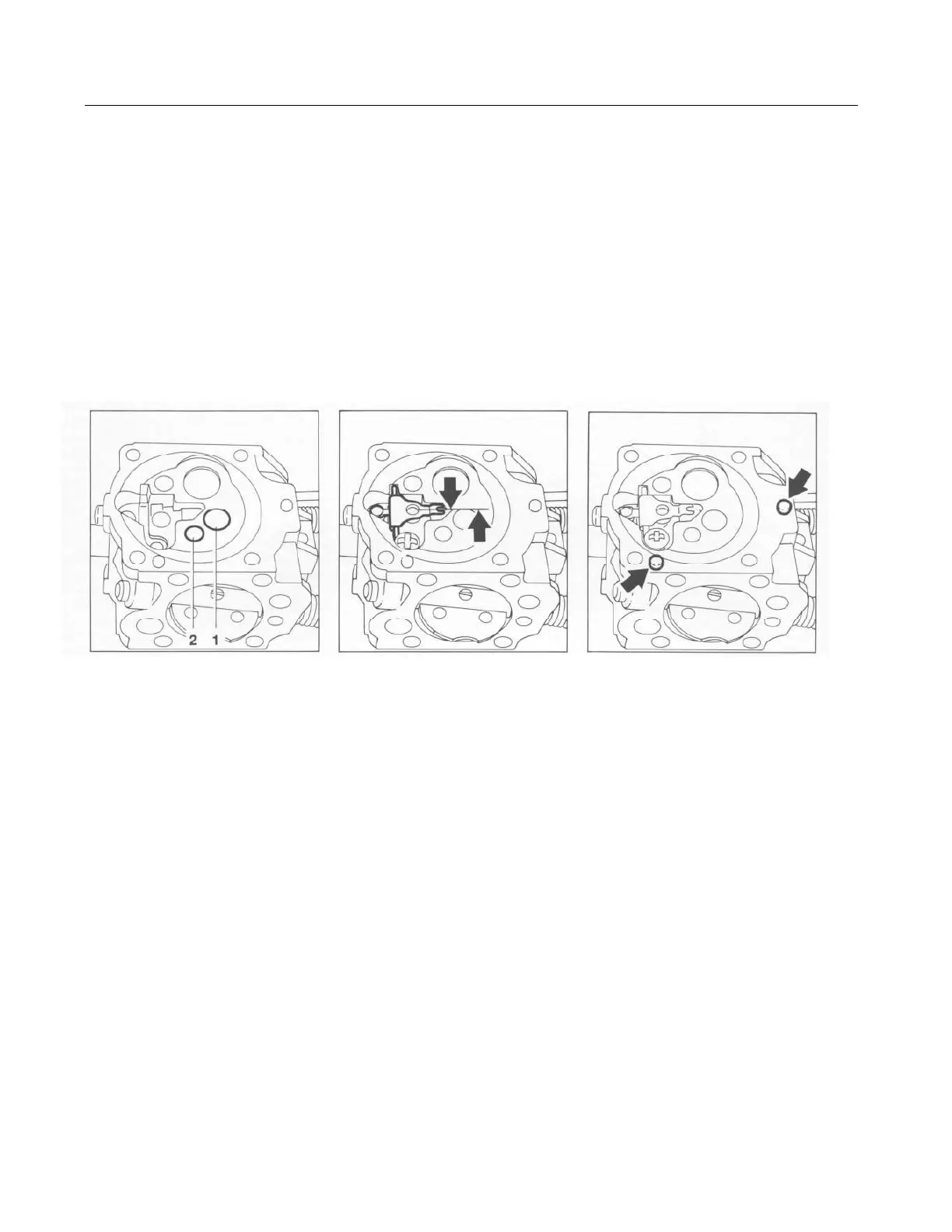
1 = Valve jet
2 = Fixed jet (066) Correct position of inlet control lever Locating pegs on body
- When inserting the valve jet and - Fit the inlet needle and the heli- - Fit the gasket, metering dia-
fixed jet, make sure they are cal spring in their respective phragm and end cover. The
exactly vertical in their bores. bores. Insert spindle in the inlet metering diaphragm and gasket
Press the jets home until they are control lever, engage clevis in are held in position by the inte-
flush with the metering chamber. annular groove on the head of grally cast pegs on the carburetor
the inlet needle and tighten down body.
- On the 064, fit a new O-ring in the round head screw. Make sure
the bore for the fixed jet. Press that the helical spring locates on Note: An end cover with compen-
home the fixed jet, small the control lever's nipple. sator can be installed in place of
diameter first, and secure it with the normal end cover if the connec-
the retaining ring. Important: The upper edge of the for stub on the inner filter element
inlet control lever must be flush is opened up and carefully de-
Note: The fixed jet "68" (with with the metering diaphragm seat- burred.
0.68 mm orifice) installed in ing face. If necessary, use suitable
model 064 saws enables the pliers to carefully bend the lever. - Insert the fuel strainer at the
engine to be tuned for optimum pump side. Fit the pump dia-
performance up to an altitude of - Check easy action of the inlet phragm, gasket and end cover
approx. 2,000 m (6,500 ft) above control lever. and tighten down securely. The
sea level. A smaller fixed jet "64" pump diaphragm and gasket are
(high altitude jet) can be installed held in position by the integrally
for operation at higher altitudes. cast pegs on the end cover.
- - Refit the carburetor adjusting
screws.
- Carry out leakage test, see 11.3,
after installing the carburetor.