BF
English
13
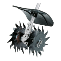
N Rotate the outer right-hand
blade (7) on the shaft until it can be
pushed into position – check the
direction of rotation again (arrows).
N Insert and engage the hitch pin (8)
in the hole in the shaft – fold the
hitch pin flat against the blade.
N Use the same procedure to mount
the rotor blades on the left-hand
side.
Not all basic power tools are equipped
with a carrying ring.
The carrying ring is available as a
special accessory.
The type of carrying ring depends on the
market and the basic power tool.
For position of carrying ring see
"Mounting the Loop Handle".
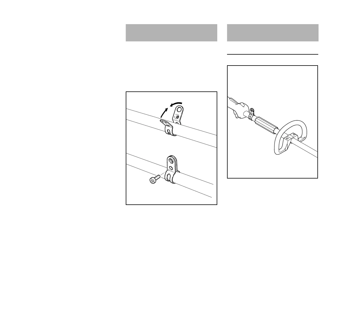
N Place the clamp (1) against the
drive tube with the tapped hole on
the left (viewed from engine).
N Squeeze the two ends of the clamp
together and hold in that position.
N Insert the M6x14 screw (2).
N Line up the carrying ring.
N Tighten down the screw firmly.
Position of Handle
A loop handle (1), sleeve (2) or a
carrying ring (3) may already be fitted to
the basic power tool.
Position of carrying ring
The carrying ring (3) on the drive tube
must be in front of the control handle.
Position of sleeve
The sleeve (2) on the drive tube acts as
a spacer.
N Slide the sleeve (2) so that it is in
front of the carrying ring.
Fitting the Carrying Ring
Mounting the Loop Handle