16 BGA 85
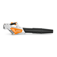
: Squeeze both sides (1) of the
spring together and fit them
under the retaining lugs (2).
– Reassemble all other parts in the
reverse sequence.
– Check operation – the spring
must push the battery about 1 cm
out of the compartment when the
locking levers are operated.
3905RA023 AM
1 2
7.5 Handle Housing
Removing
– Remove the cover, b 7.2
– Remove the right half of the
handle, making sure the trigger
switch lockout does not pop out
and the torsion spring does not
drop out of the trigger switch
lockout.
To assemble the left half of the
handle:
– Remove the trigger switch
lockout, b 7.6, trigger, b 7.7,
switch, b 9.2, wiring harness,
b 9.5, and retaining latch,
b 7.8
– Check both halves of handle and
replace as necessary.
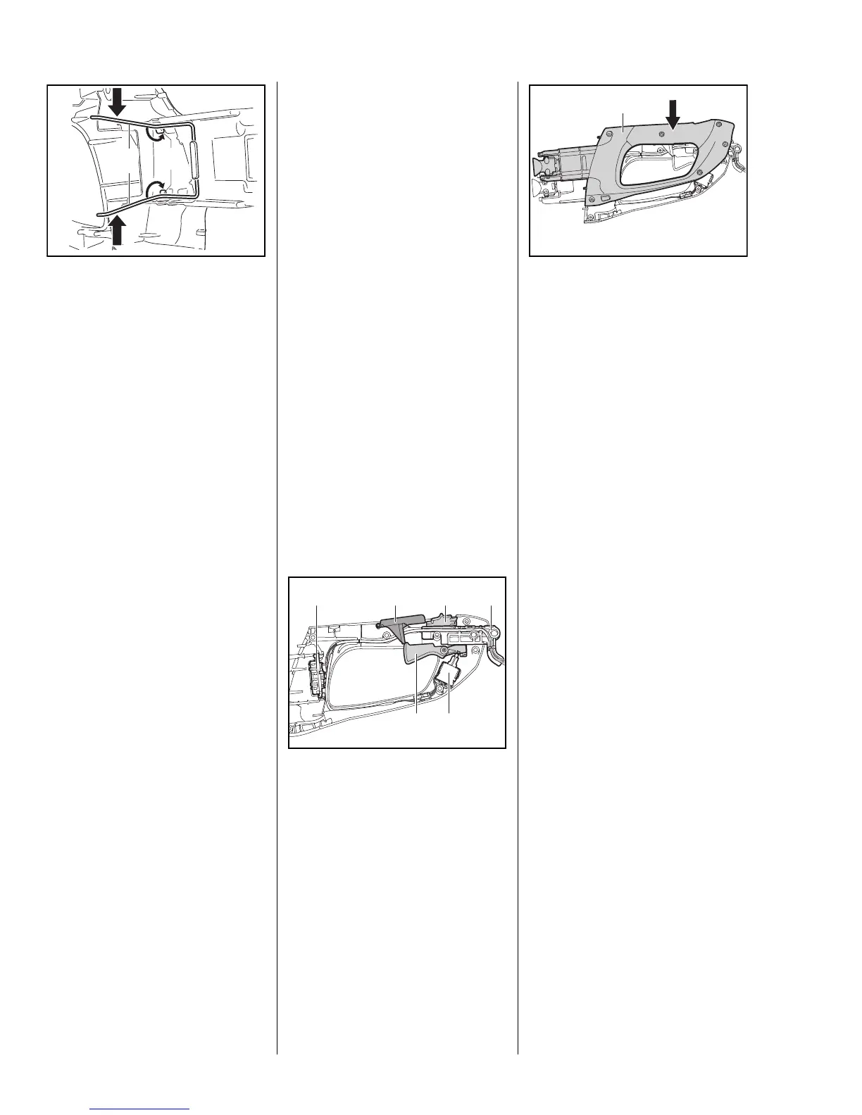
Installing
: Install the retaining latch (1),
b 7.8, wiring harness (2) with
contact plate and adapter (3),
b 9.5, trigger (4), b 7.7,
switch (5), b 9.2, and trigger
switch lockout (6), b 7.6, in the
left half of the handle.
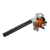
: Place the right half of the
handle (1) on the left half, making
sure they fit exactly and no wires
are pinched.
– Fit the cover, b 7.2
– Check operation of trigger:
Move the retaining latch to ‚,
depress the trigger switch lockout
and trigger – it must be possible
to depress the trigger as far as
stop.
– Check operation of retaining
latch:
Set retaining latch to ƒ – trigger
cannot be pulled when the trigger
switch lockout is depressed.
9927RA035 GM
1
 Loading...