41BT 130
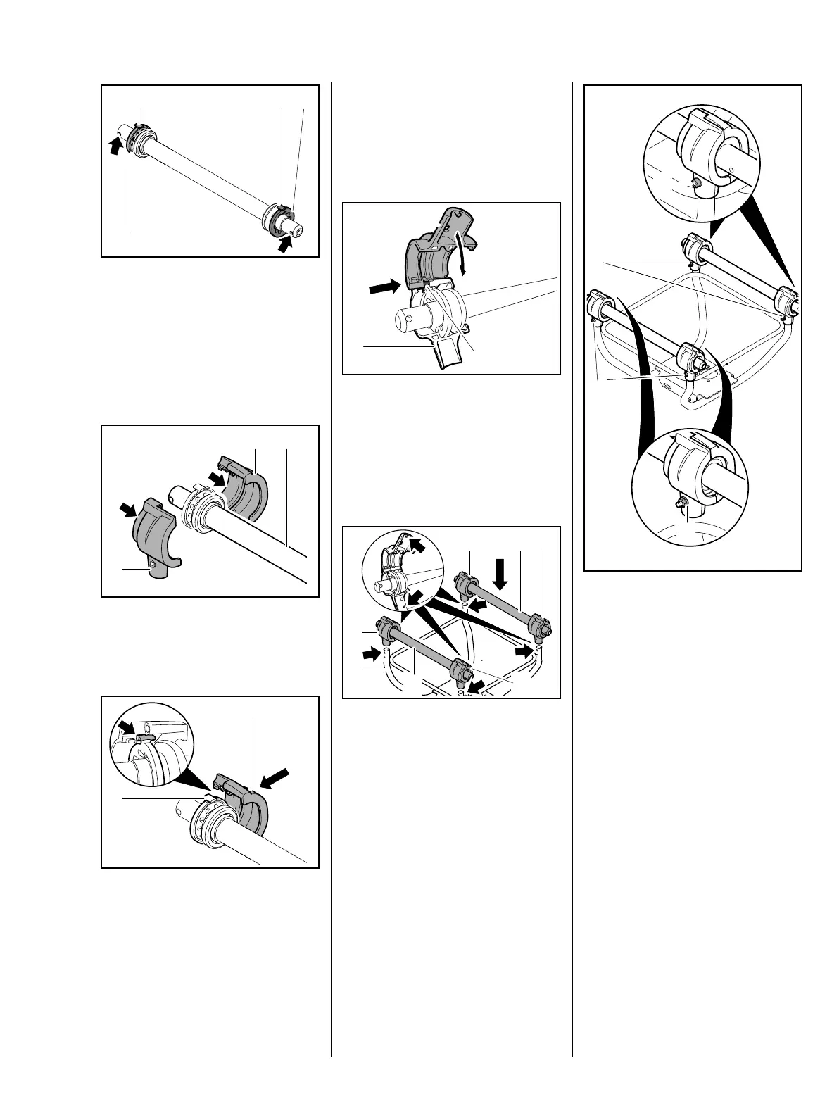
: Line up the rubber buffers (1) so
that the tabs (2) face upwards
and are offset 90° from the cross
holes (arrows).
The labels on the tubes must face
upwards.
Fit the AV housings (2) on each
tube (1) so that their smaller outside
diameters (arrows) face outwards.
– Use STIHL OH 723 press fluid to
simplify assembly, b 13
2
9912RA176 TG
2
1
1
1
9912RA177 TG
2
2
1
2
9912RA178 TG
: Position the inboard halves of the
AV housing (1) so that the rubber
buffer's tab (2) engages the
recess (arrow) and hold in that
position.
: Slide the outboard halves of the
AV housings (1) with pin (2) into
place and swing them down,
making sure the rubber buffer
and stop engage their seats
inside the AV housings (1).
: Fit the tubes (1) with AV
housings (2) on the handle
frame (3) so that the inboard
fixing pins (arrows) engage the
holes (arrows) in the handle
frame (3).
9912RA179 TG
1
1
2
1
1
3
22
2
2
9912RA180 TG
: Insert screws (1) from the
outboard sides, then fit the new
locknuts (2) and tighten them
down firmly.
– Mount the outer handle tubes,
b 11.1
– Reassemble all other parts in the
reverse sequence.
9912RA270 TG
2
1
2
1
 Loading...