27BT 130
5.4 Pins
The pins guarantee the security of
the brake spring and brake lever.
Worn pins must be replaced – the
brake spring may pop out during
this operation.
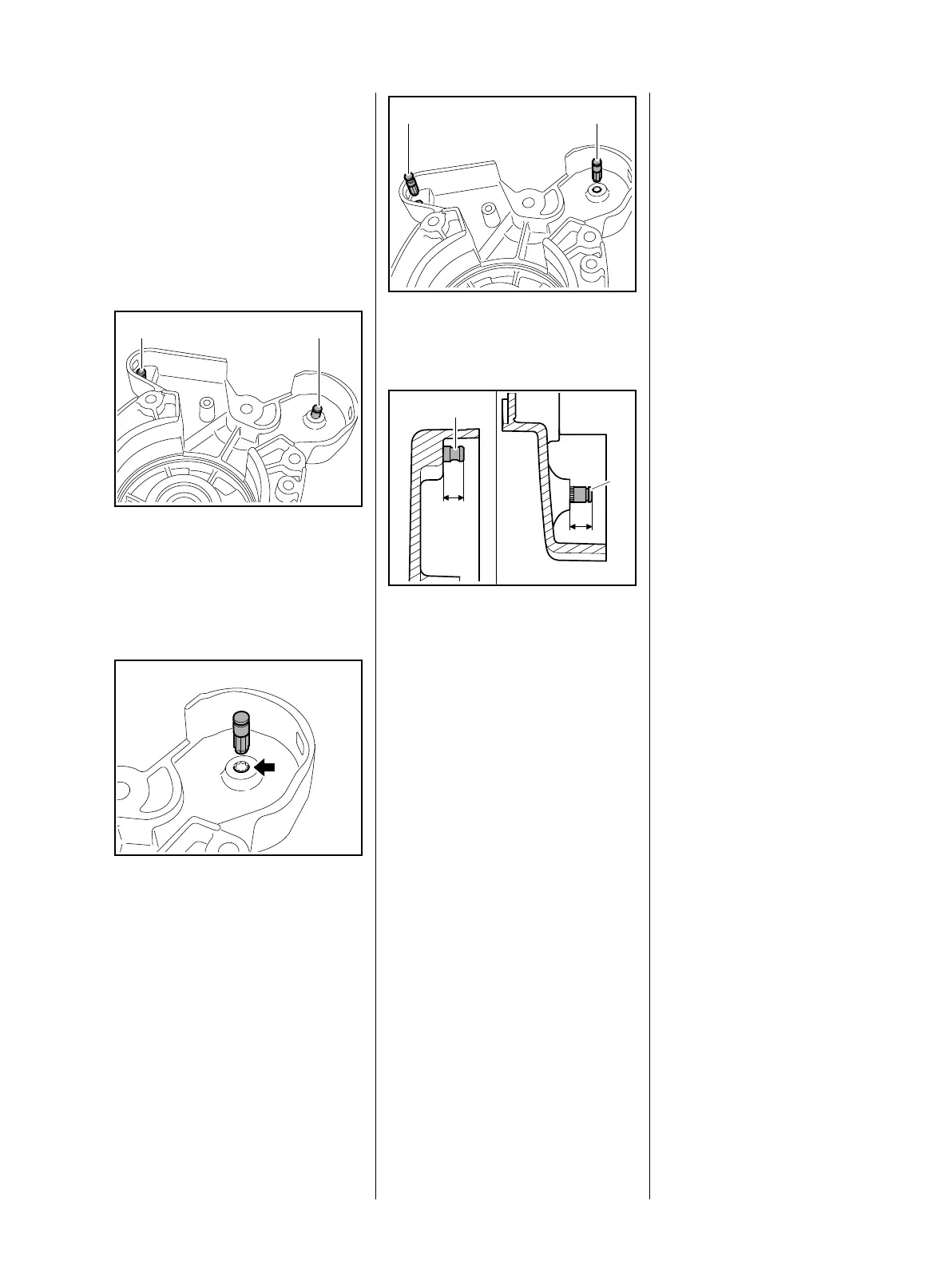
– Remove the brake lever, b 5.3
: Use a 3 mm punch to drive out
the pins (1, 2) from the other side
of the housing.
Installing
The pins must be driven home
squarely.
– Before installing the new pin, coat
its knurled shank with
threadlocking adhesive, b 13
: Position the new pin in the bore
(arrow) so that the knurling on the
pin meshes with the knurling in
the clutch housing.
9912RA046 TG
1 2
9912RA047 TG
: Drive home the pins (1 and 2) as
specified below.
: Pin (1) a = about 5.7 - 5.9 mm
Pin (2) b = about 7.0 - 7.2 mm
– Lubricate the brake lever with
STIHL multipurpose grease,
b 13
– Reassemble all other parts in the
reverse sequence.
9912RA048 TG
21
9912RA049 TG
a
b
2
1
 Loading...