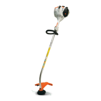
44 BT 130
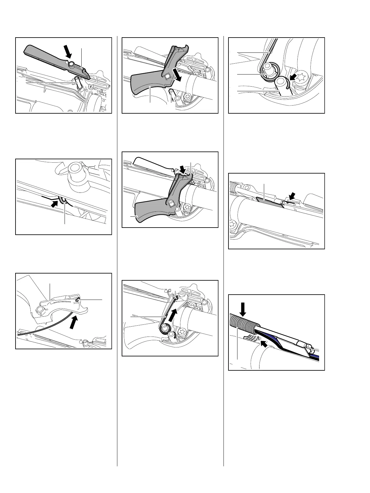
: Push the lockout lever (1) onto
the pivot pin (2) and attach the
torsion spring's upper leg.
: The torsion spring (1) must
engage the notch (arrow).
: Attach the throttle cable (1) to the
trigger (2).
– Turn the throttle trigger 90°
counterclockwise.
– Push the handlebar home, line it
up and secure it position, b 10.1
1
9912RA286 TG
2
1
9912RA287 TG
1
2
9912RA288 TG
: Push the throttle trigger (1) onto
the pivot pin (2).
: Position the throttle trigger (1) so
that the step on its lug (2)
engages the lockout lever
(arrow).
: Push the torsion spring (1) under
the throttle cable (2).
1
2
9912RA289 TG
1
2
9912RA290 TG
1
9912RA291 TG
2
: Push the torsion spring (1) onto
the pin (2) as far as stop.
The curved leg (arrow) must locate
on the peg (3).
: Push the slide (1) into its seat so
that it engages the center of the
toothing (arrow).
The protective tube (1) must be
properly seated in the convolutions
of the handle molding.
: Push the short circuit and ground
wires into the guide (arrow), then
fit the protective tube (1).
9912RA292 TG
3
2
1
9912RA293 TG
1
1
9912RA294 TG
 Loading...