•
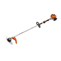
Rotate spindle (1) counterclock-
wise until the crankshaft comes
out of the ball bearing. The two
halves of the crankcase are
separated in this process.
•
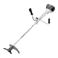
Puller (1) 4119 890 4600 can be
used in place of the ZS installing
tool. It is mounted to the clutch
side of the crankcase wit M6x20
screws (2).
•
Turn thrust bolt (3) clockwise
until the crankshaft is released
from the ball bearing.
FS 120...350, FR 350
- Back off spindle (left-hand thre-
ad) of ZS installing tool
5910 890 2220 a little.
•
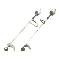
Place extension (1) 4116 894
1000 on crankshat stub and
sleeve (2) 1123 851 8300 on
bores at starter side of crank-
case.
•
Hold ZS installing tool (1)
5910 890 2220 against starter
side of crankcase so that the
notch marked "16" is at the
bottom.
•
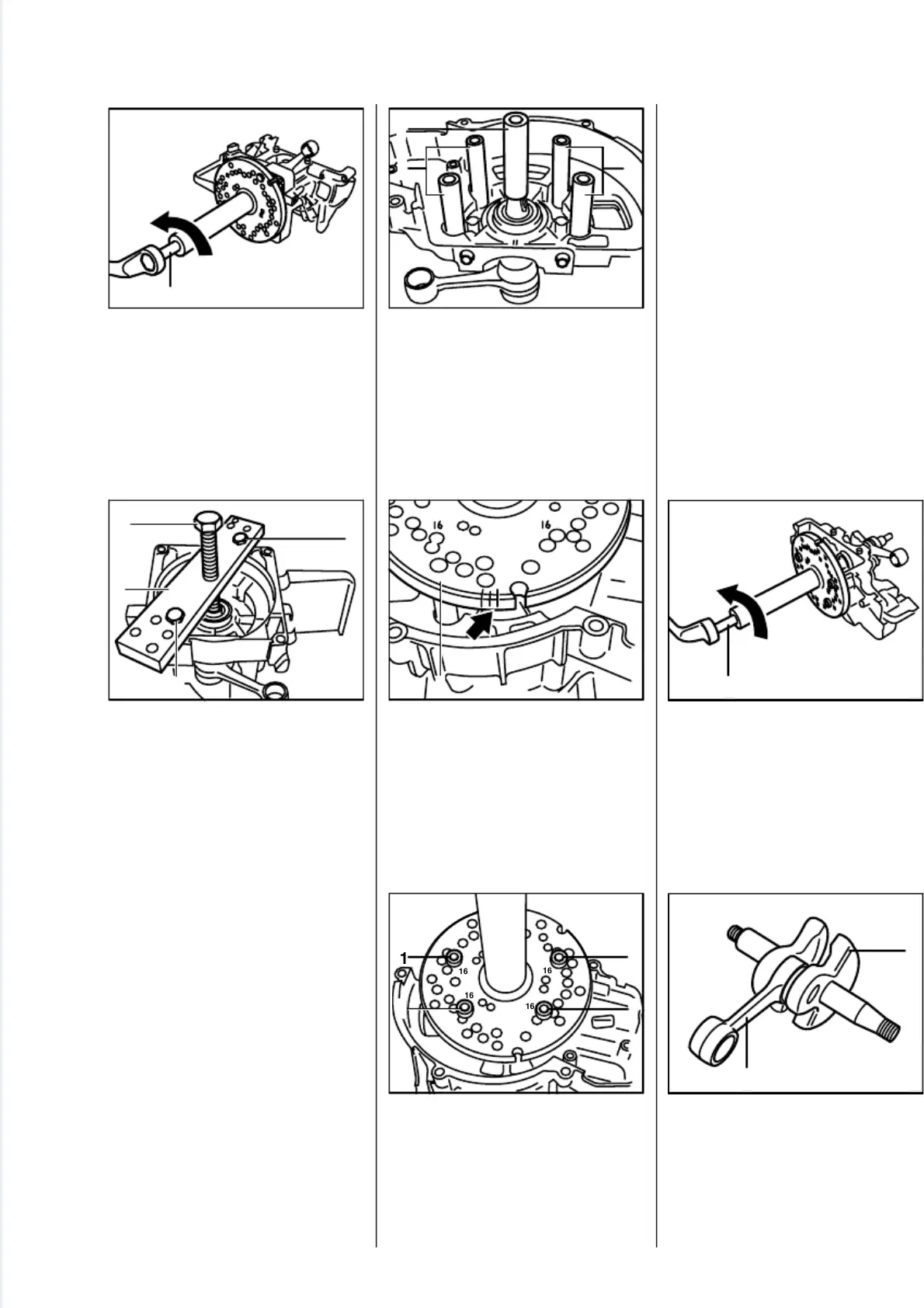
Insert screws (1) 9022 341 1190
(from ZS installing tool kit) in
holes marked "16", fit washers at
other side and screw on nuts.
FS 400/450, FR 450
- Hold ZS installing tool against
starter side of crankcase so that
the notch marked "17" is at the
bottom.
- Insert M5x60 screws in holes
marked "18", fit washers at other
side and screw on nuts.
All models
•
Rotate spindle (1) counterclock-
wise until the crankshaft comes
out of the ball bearing.
•
The crankshaft (1), connecting
rod (2) and needle bearing form
an inseparable unit. It must
always be replaced as a com-
plete unit.
2
5
0
R
A
0
6
1
1
V
A
2
5
0
R
A
0
6
5
1
3
2
2
V
A
2
5
0
R
A
0
5
8
2
1
2
V
A
16
2
5
0
R
A
0
5
9
1
V
A
2
5
0
R
A
0
6
0
1
16
16
16
16
1
1
1
V
A
2
5
0
R
A
0
6
4
1
V
A
2
5
0
R
A
0
6
6
2
1
V
A
FS 120, 200, 300, 350, 400, 450, FR 350, 450 19

 Loading...