•
Press down the lever.
•
Pull out the flexible shaft.
•
Release the clamp screw (1).
•
Pull off the housing (2).
- Service the housing - see
"Standard Repairs, Trouble-
shooting" handbook.
Reassemble in the reverse
sequence.
- Degrease clamp mounting area.
- Tighten down clamp screw to
4.5 Nm (3.3 lbf.ft).
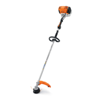
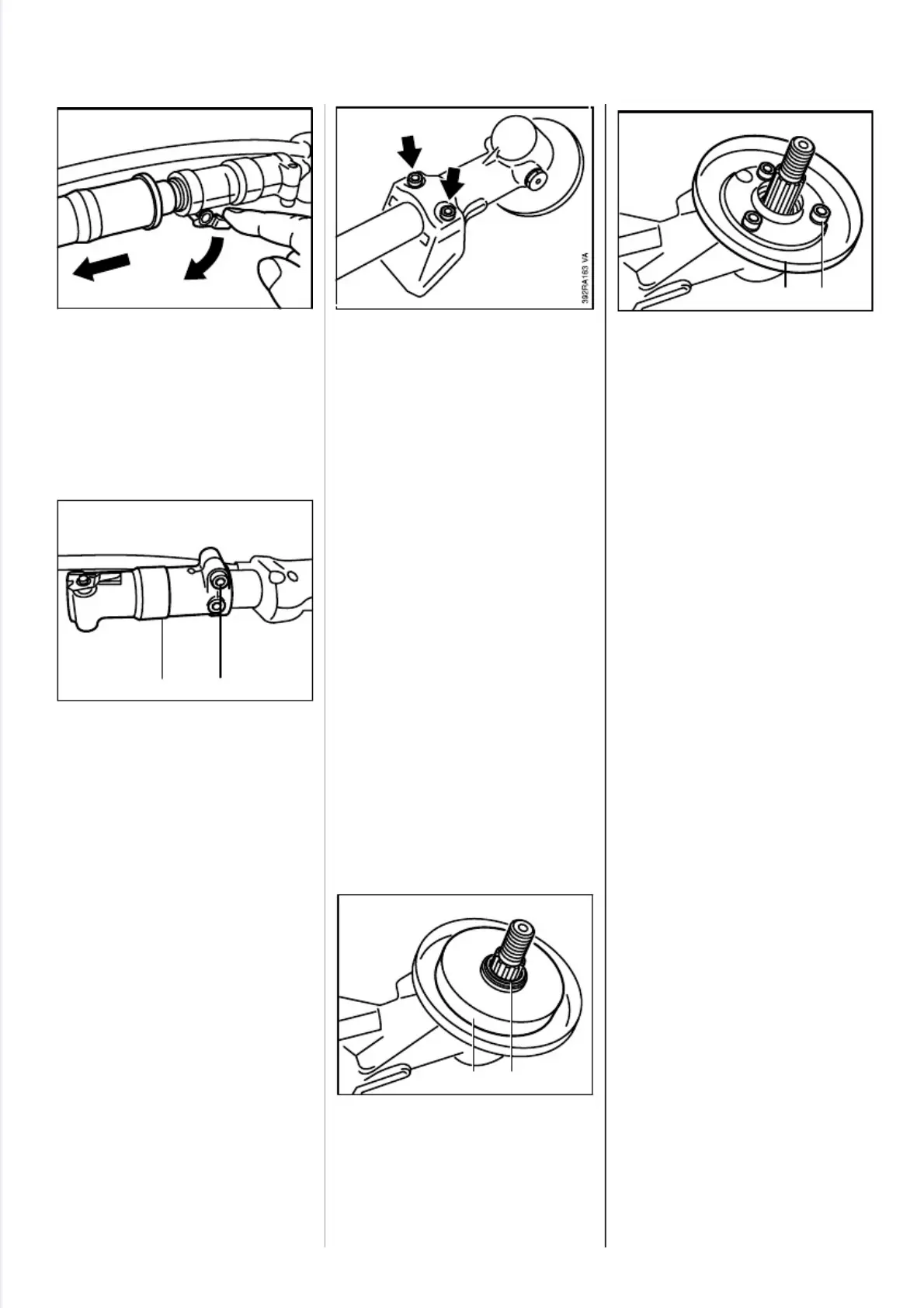
Illustration shows FS 120/200
gearhead.
- Remove deflector or stop, if fitted.
•
Release clamp screws.
- Pull gearhead off the drive tube.
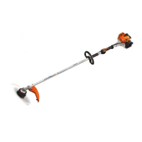
FS 300...450
•
Remove retainer (1) - if fitted -
and thrust washer (2) from the
output shaft.
•
Take out screws (1).
•
Remove the guard ring (2).
- For other disassembly and
assembly procedures see
"Standard Repairs and Trouble-
shooting" handbook.
- On FS 300...450, tighten down
screws on guard ring to 5.0 Nm
(3.7 lbf.ft).
- Install a new retainer.
- Degrease clamp mounting area.
- Slide the gearhead onto the
drive tube - turn the output shaft
back and forth at the same time
so that the square end of the
drive shaft engages the square
socket in the drive pinion.
- Push the gearhead as far as
stop and line it up.
- On FS 120/200 and FR 350/450,
tighten down clamp screws to
8.5 Nm (6.3 lbf.ft).
- On FS 300...450, first tighten
clamp screws to 1.5 Nm (1.1
lbf.ft) and then finally tighten
them down to 7.5 Nm (5.5 lbf.ft).
- Refit the deflector or stop.
2
5
0
R
A
2
1
0
12
V
A
2
5
0
R
A
2
0
9
12
V
A
10.7 Housing (FR 350/450) 11. CUTTING TOOL DRIVE
11.1 Gearhead
2
5
0
R
A
2
4
3
V
A
2
5
0
R
A
2
4
4
2 1
V
A
56 FS 120, 200, 300, 350, 400, 450, FR 350, 450
 Loading...