FS 260 C, FS 360 C
English
23
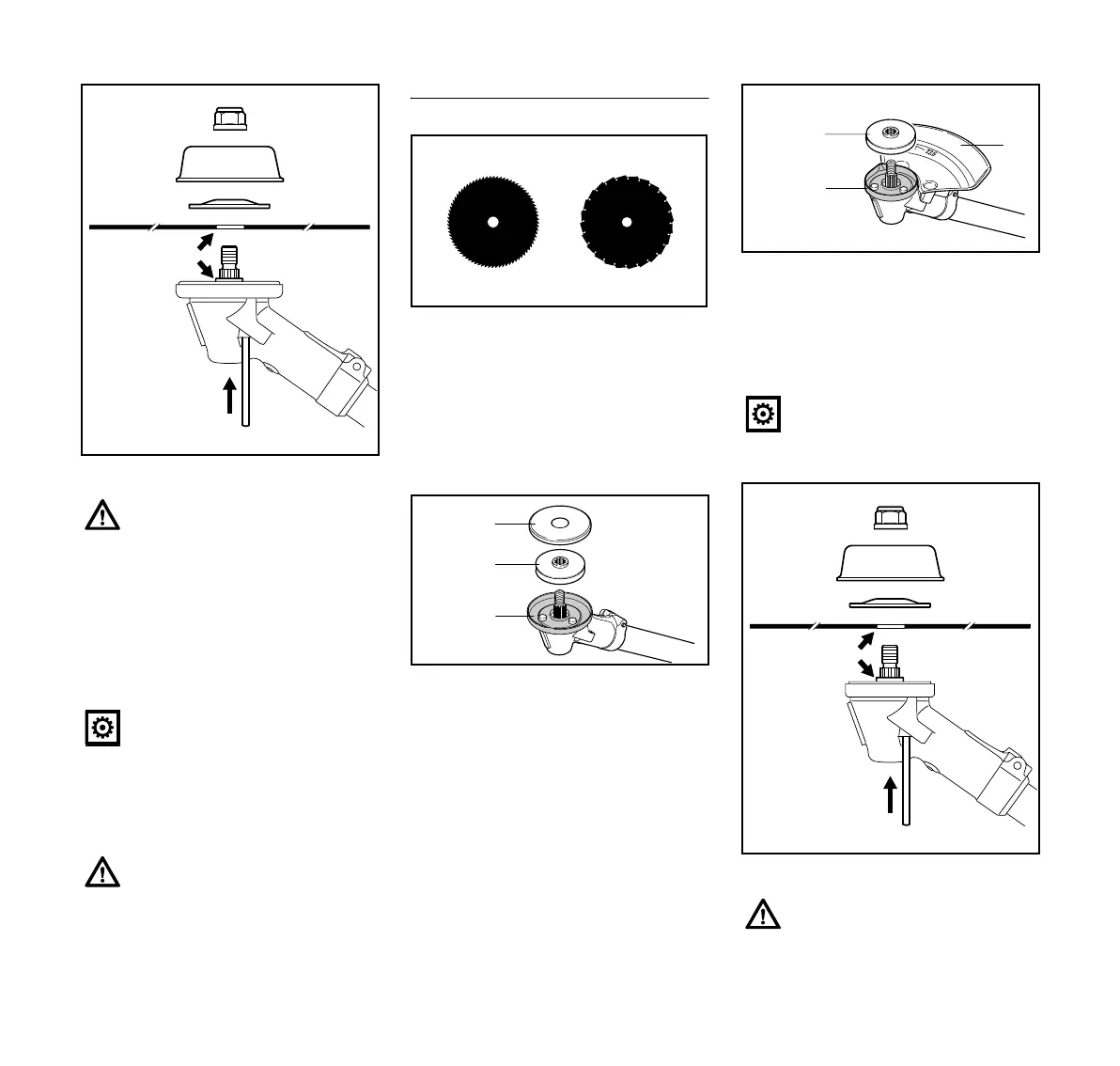
N Position cutting attachment (1)
N Fit the thrust washer (2) – curvature
faces upward
N Position thrust plate (3)
N Block the shaft
N Screw on the nut (4)
counterclockwise and tighten
Removing cutting attachments
N Block the shaft
N Unscrew the nut clockwise
Attaching circular saw blades
With circular saw blades, the cutting
edges must face clockwise.
For attaching circular saw blades, a limit
stop set is available as a special
accessory that contains a limit stop and
a guard ring for circular saw blades.
Change guard ring
N Remove guard washer (3) and
thrust plate (4)
N Remove guard ring (5) for mowing
tools
N Attach guard ring (6) for circular saw
blades
N Push thrust plate (4) onto the shaft
N Attach limit stop (7) for circular saw
blades
Mounting the cutting attachment
N Position cutting attachment (1)
The collar (a) must engage the
hole (b) in the cutting attachment!
Remove the tool used to block the
shaft.
A nut that moves too easily should
be replaced.
2
3
1
4
002BA409 KN
b
a
681BA165 KN
002BA424 KN
4
3
5
Do not use the guard washer (3)
for circular saw blades.
The collar (a) must engage the
hole (b) in the cutting attachment!
7
002BA425 KN
6
4
2
3
1
4
002BA423 KN
b
a
 Loading...