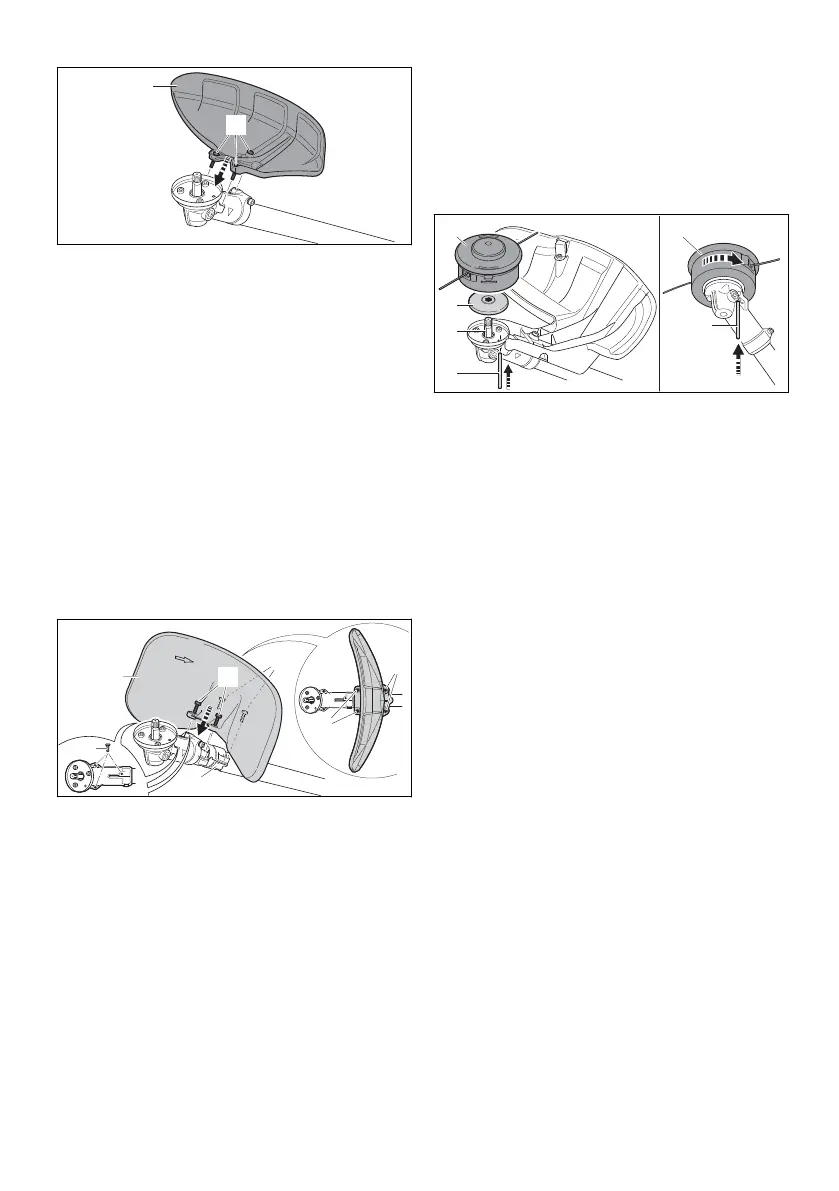
► Position the guard (1) on the gear housing.
► Insert the screws (2) and tighten them down to
a torque of 10 Nm.
6.2.2 Removing deflector for mowing heads,
metal cutting attachments and limit
stop
► Shut off the engine.
► Take out screws.
► Remove guard.
6.2.3 Mounting deflector for shredder blade
An additional holder is required on the shaft to
attach the deflector. The holder is attached to the
shaft with special screws and special tools.
► Shut off the engine.
► If the holder for the guard has not yet been fit‐
ted to the shaft: Have the holder fitted by a
STIHL dealer.
► Place the guard (1) on the holder (2) so that
the curved side faces inwards towards the
gear unit housing.
► Insert the screws (3) and tighten them down to
a torque of 10 Nm.
► Press plugs (4) into the threaded holes on the
gear unit housing.
The threaded holes are protected from dirt.
6.2.4 Dismantling the guard for shredder
blades
► Shut off the engine.
► Take out screws.
► Remove guard.
► Pull the plug out of the threaded holes on the
gear unit housing and press it into the threa‐
ded holes of the bracket.
The threaded holes of the bracket are protec‐
ted against dirt.
6.3 Mounting and Removing the
Mowing Head
6.3.1 Mounting the Mowing Head
► Shut off the engine.
► Place the thrust plate (2) on the shaft (3) so
that its smaller diameter faces up.
► Fit the mowing head (1) on the shaft (3) and
turn it counterclockwise by hand.
► Insert the stop pin (4) in the bore up to the limit
stop and hold it depressed.
► Turn the mowing head (1) counterclockwise
until the stop pin (4) engages in position.
The shaft (3) is now blocked.
► Tighten down the mowing head (1) firmly by
hand.
► Remove the stop pin (4).
6.3.2 Removing the Mowing Head
► Shut off the engine.
► Insert the stop pin in the bore as far as stop
and hold it depressed.
► Rotate the mowing head until the stop pin
engages in position.
The shaft is now blocked.
► Unscrew the mowing head clockwise.
► Remove the thrust plate.
► Remove stop pin.
6.4 Removing and Installing Metal
Cutting Attachment
6.4.1 Mounting grass cutting blade, brush
knife or circular saw blade
► Shut off the engine.
English 6 Assembling the Trimmer
12 0458-856-0121-A. VA0.B21.

 Loading...