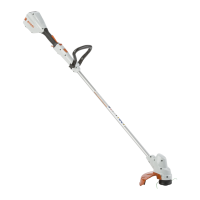
► Position the mowing head (1) on the shaft (2).
► Hold the mowing head (1) with your hand.
► Manually rotate the upper part (3) clockwise
and tighten it.
Removing the Mowing Head
► Switch off the brushcutter and remove the bat‐
tery.
► Hold the mowing head with your hand.
► Manually rotate the upper part counterclock‐
wise until the mowing head can be removed.
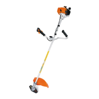
7.4.3 DuroCut 5-2 mowing head:
Mounting the Mowing Head
► Switch off the brushcutter and remove the bat‐
tery.
► Place the thrust plate (2) on the shaft (3) so
that its smaller diameter faces up.
► Position the mowing head (1) on the shaft (3).
► Hold the fanwheel (4) with your hand.
► Manually rotate the mowing head (1) clock‐
wise and tighten it.
Removing the Mowing Head
► Switch off the brushcutter and remove the bat‐
tery.
► Hold the fanwheel with your hand.
► Unscrew the mowing head counterclockwise.
► Remove the thrust plate.
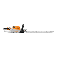
8 Adjusting Trimmer for User
8.1 Adjusting and Setting the Loop
Handle
The loop handle can be set to different positions
to suit the height and reach of the user.
► Switch off the brushcutter and remove the bat‐
tery.
► Undo the screws (2).
► Move the loop handle (1) to the required posi‐
tion and check that the following conditions
are met:
–
The bump guard (3) fits between the loop
handle (1) and the control handle.
–
a = no more than 30 cm.
► Tighten down the screws (2) so that the loop
handle (1) cannot be rotated on the shaft.
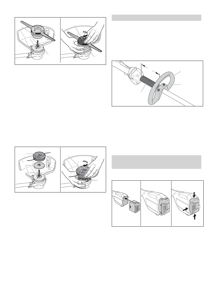
9 Removing and Fitting the
Battery
9.1 Fitting the Battery
► Insert the battery (1) in the battery compart‐
ment (2) and press it home until you hear a
click.
Arrows (3) on battery (1) are still visible and
battery (1) is held securely in battery compart‐
ment (2). There is no electrical contact
between the trimmer and battery (1).
► Push the battery (1) into the battery compart‐
ment (2) as far as stop.
The battery (1) engages with a second click
and is flush with the trimmer’s housing.
8 Adjusting Trimmer for User English
0458-832-0121-B. VA0.B21. 13

 Loading...