0458-683-0121-A
5
English
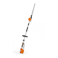
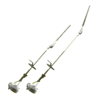
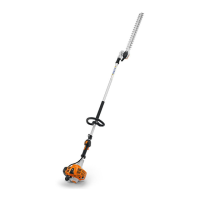
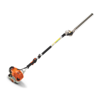
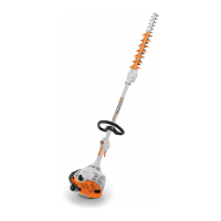
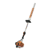
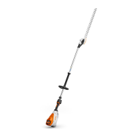
3 Overview
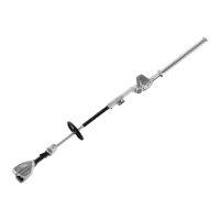
1Shaft
The shaft connects all components.
2 Handle hose
For holding and controlling the long-reach hedge
trimmer.
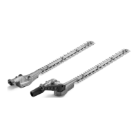
3 Cutting blades
The cutting blades cut the hedge.
4 Blade scabbard
The blade scabbard protects against contact with the
cutting blades.
5Screw plug
The screw plug closes the filler opening for STIHL gear
grease.
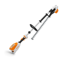
6 Swivel handle
Serves to adjust angle of cutting blades.
7 Sliding sleeve
Unlocks the blade angle adjuster.
8 Locking lever
The locking lever holds the battery in the battery
compartment.
9 Battery compartment
The battery compartment holds the battery.
10 Cover
The cover is the placeholder for a Smart Connector 2 A.
11 Trigger lockout
The trigger lockout unlocks the trigger.
12 Release slide
The release slide is used to switch on the long-reach
hedge trimmer.
13 LED
The LEDs indicate the selected power level.
14 Carrying ring
For attaching the carrying system to the brushcutter.
15 Trigger
Switches the long-reach hedge trimmer on and off.
16 Control handle
For operating, holding and controlling the long-reach
hedge trimmer.
17 Air filter
The air filter filters the air entering the engine.
18 LEDs
The LEDs indicate the state of charge of the battery and
any faults.
19 Battery
Supplies power to the long-reach hedge trimmer.
20 Button
The button activates the LEDs on the battery.
# Rating plate with machine number
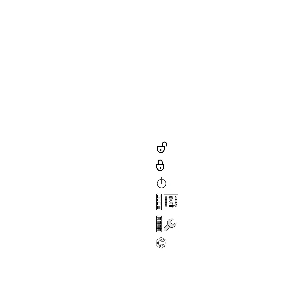
3.3 Icons
The symbols, which may be on the long-reach hedge
trimmer and battery, have the following meaning:
The clamp nut is unscrewed in this position. The shaft
can be extended.
The clamp nut is locked in this position. The shaft
cannot be extended.
This icon marks the release slide.
1 LED lights up red. The battery is too warm or
too cold.
4 LEDs flashing red. There is a fault in the
battery.
Guaranteed sound power level in accordance
with Directive 2000/14/EC in dB(A) for the
purpose of comparing the sound emissions of
products.
L
W
 Loading...