UM1879 Rev 4 15/41
UM1879 Hardware layout and configuration
40
10.1.4 Using ST-LINK/V2-1 to program/debug an external STM32 application
board
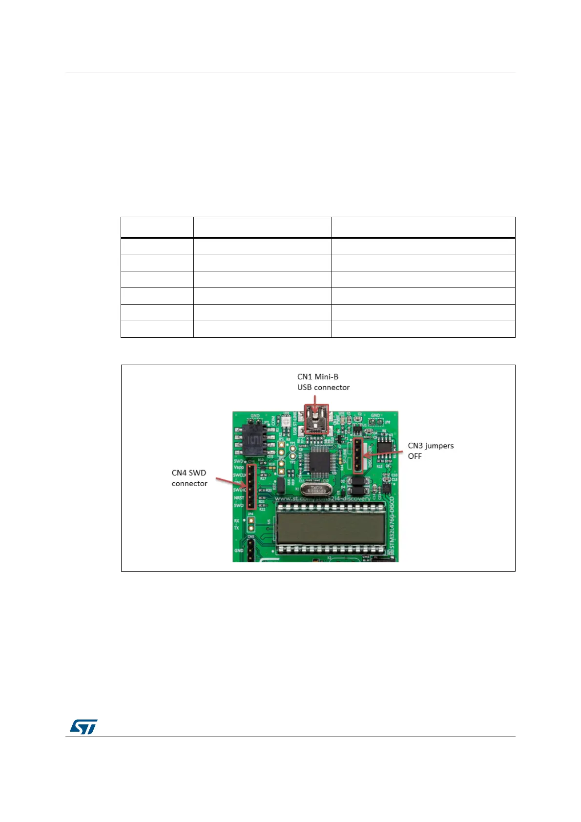
To use the ST-LINK/V2-1 to program the STM32 on an external application board (out of the
STM32L476VGT6 on board), remove the two jumpers from CN3 as shown in
Figure 7 in
red, and connect the board to the CN4 software debug connector according to Table 4.
Make sure the jumpers JP6.3V3, and JP5.OFF are set.
JP3, must be ON if CN4 pin 5 (NRST) is used in the external application board.
Figure 7. CN1, CN3 (OFF), CN4 connections
Table 4. Debug connector CN4
Pin CN4 Designation
1 Vapp VDD from application
2 SWLCK SWD clock
3 GND Ground
4 SWDIO SWD data input/output
5 NRST RESET of target MCU
6SWO Reserved