UM1879 Rev 4 23/41
UM1879 Hardware layout and configuration
40
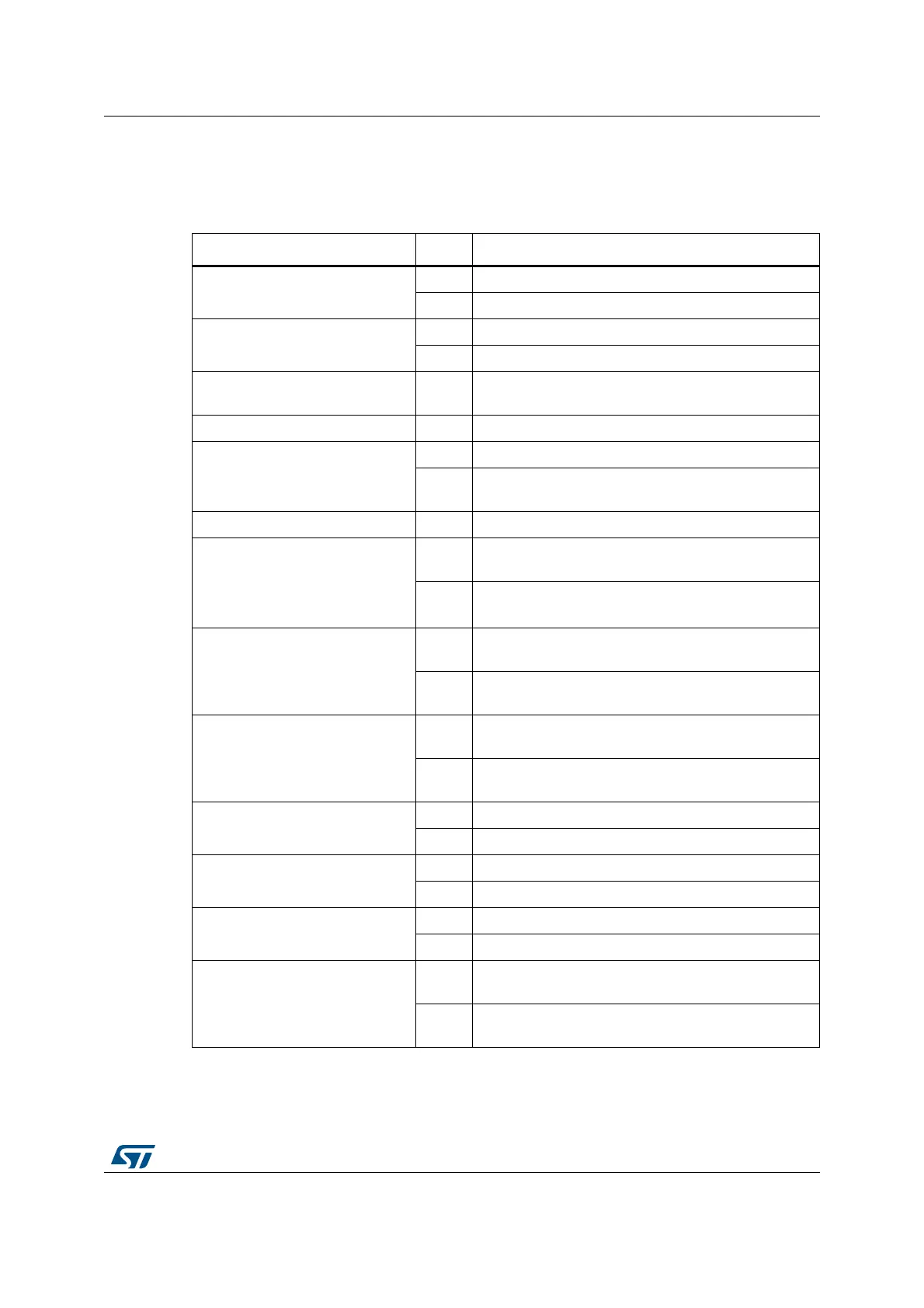
10.15 Solder bridges
Table 8 describes each solder bridge. The default state is indicated in bold.
Table 8. Solder bridges
Bridge State Description
SB1 (ST-LINK PWR)
ON ST-LINK module is powered
OFF ST-LINK module is not powered
SB2 (EXT/RF E2P)
ON 5V connected to CN2.8
OFF 5V is not connected to CN2.8
SB3, SB4, SB7, SB8
(RESERVED)
OFF Reserved, do not modify
SB5, SB6, SB9, SB10 (DEFAULT) ON Reserved, do not modify
SB11 (STM_RST)
ON No incidence on NRST signal of STM32F103CBT6
OFF
NRST signal of STM32F103CBT6 is connected to
GND
SB12 OFF Reserved
SB16, SB13 (USART RX, TX)
ON
PA2, PA3 of STM32F103CBT6 are connected to PD6,
PD5 of STM32L476VGT6
OFF
PA2, PA3 of STM32F103CBT6 are not connected to
PD6, PD5 of
STM32L476VGT6
SB17, SB15 (MFX USART RX,TX)
ON
PA2, PA3 of STM32L476VGT6 are connected to MFX
USART RX,TX
OFF
PA2, PA3 of STM32L476VGT6 are not connected to
MFX USART RX,TX
SB14 (T_SWO)
ON
PA10 of STM32F103CBT6 is connected to PB3 of
STM32L476VGT6
OFF
PA10 of STM32F103CBT6 is not connected to PB3 of
STM32L476VGT6
SB18 (MCO)
ON If SB22 is also ON, MCO is connected to PH0
OFF MCO is not connected to PH0
SB19, SB20 (32.768kHz CLK)
ON PC14, PC15 are connected to X3 crystal
OFF PC14, PC15 are not connected to X3 crystal
SB21, SB22 (8MHz CLK)
ON PH0, PH1 are connected to X2 crystal (X2 is not fitted)
OFF PH0, PH1 are not connected to X2 crystal
SB23 (B1-RESET)
ON
B1 push-button is connected to NRST of STM32L476
Discovery board
OFF
B1 push-button is not connected to NRST of
STM32L476 Discovery board