Hardware layout and configuration UM1879
24/41 UM1879 Rev 4
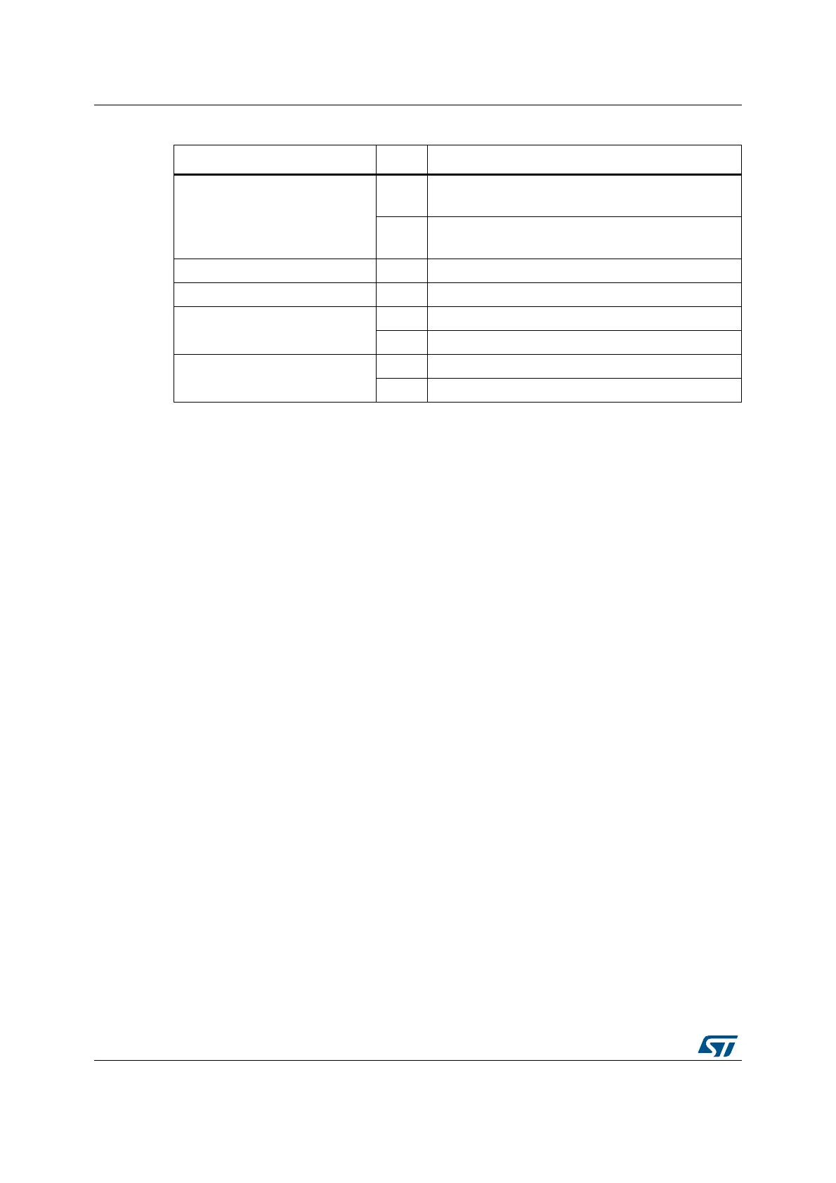
SB24, SB25 (OTG FS)
ON
OTG_FS_VBUS signal is connected to PA9
OTG_FS_ID signal is connected to PA10
OFF
OTG_FS_VBUS signal is not connected to PA9
OTG_FS_ID signal is not connected to PA10
SB26 ON Reserved, do not modify
SB27 OFF Reserved, do not modify
SB28 (2.5V REG inhibit)
ON U12 (2.5V regulator) input is inhibited
OFF U12 input is not inhibited
SB29 (2.5V REG input)
ON 5V is connected to U12 input
OFF 5V is not connected to U12 input
Table 8. Solder bridges (continued)
Bridge State Description