UM1879 Rev 4 19/41
UM1879 Hardware layout and configuration
40
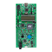
10.5 User interface: LCD, joystick, LEDs
The STM32L476 Discovery board features sept LEDs with the following functionalities:
• LD1 COM: LD1 default status is red. LD1 turns to green to indicate that
communications are in progress between the PC and the ST-LINK/V2-1
• LD2 PWR: the red LED indicates that the board is powered
• LD3 OC: the red LED indicates a fault when the board is in current limit (510 mA)
• LD4 user: the red LED is a user LED connected to the I/O PB2 of the
STM32L476VGT6
• LD5 user: the green LED is a user LED connected to the I/O PE8 of the
STM32L476VGT6
• LD6, LD7: USB OTG FS LEDs, see Section 10.8
Four-direction joystick (B2) with selection and a reset push-button (B1) are available as
input devices.
An LCD 4x24 segments, 4 commons, multiplexed 1/4 duty, 1/3 bias is mounted on the
DIP28 connector U5.
10.6 Boot0 configuration
Boot0 is by default grounded through a pull-down R91.
It is possible to set Boot0 high, removing R91 and putting a jumper between P1 header
pin 6 BOOT0 and pin 5 3V.
10.7 Quad-SPI NOR Flash memory
128-Mbit Quad-SPI NOR Flash memory is connected to Quad-SPI interface of
STM32L476VGT6.
10.8 USB OTG FS
The STM32L476 Discovery board supports USB OTG Full Speed communication via a USB
Micro-AB connector (CN7) and a USB power switch (U14) connected to VBUS. The board
can be powered by this USB connection as described in
Section 10.2.
A green LED LD6 will be lit in one of these cases:
• The power switch (U14) is ON and STM32L476 Discovery board works as a USB host
• VBUS is powered by another USB host when STM32L476 Discovery board works as a
USB device
Red LED LD7 will be lit when an overcurrent occurs.
In order to connect the OTG_FS_VBUS and OTG_FS_ID signals from the connector CN7 to
the OTG FS hardware IP of STM32L476VGT6, remove the LCD from its socket U5, and
close SB24 and SB25.
The default configuration is: the LCD is connected to U5, and SB24 and SB25 are opened.
In this case the OTG_FS_VBUS and OTG_FS_ID signals from CN7 are connected to the
OTG FS peripheral of the STM32L476VGT6 available on PC11 and PC12.

 Loading...