- 36 -
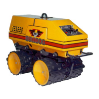
5. RADIO SET
Bulldog
®
5.1 OPERATING PRINCIPLE
When operating this machine in the remote mode the
machine functions are being manipulated through
radio frequency (RF) control. Information is being
transmitted from the transmitter (handset) to the
receiver. This information is decoded and is used to
manipulate relays and switches which control engine
and machine functions.
5.2 IDENTIFICATION NUMBERS
The address codes and the radio frequency of the
transmitter and the receiver must match for the
machine to work properly. This is done to assure that
only one transmitter can control one receiver and that
multiple machines can be used on a job site without
any interference. The ID numbers for each
component can be found as follows:
Transmitter - Located in two places:
1. Decal on the back of the case.
2. Decal on the circuit board inside the case.
Receiver - Located in two places:
1. Decal outside cover of the receiver
enclosure.
2. Decal on circuit board inside enclosure.
5.3 COMPONENTS
The radio set is comprised of three essential
components:
1. Transmitter - Handset used to control
machine operations by sending information
to the receiver.
2. Antenna - Machine mounted device which
receives and directs the transmitter signal to
the receiver.
3. Receiver - Machine mounted enclosure
which receives instructions from transmitter
and transforms this information into switch
manipulation causing the machine to operate
as instructed
5.4 OPERATING INSTRUCTIONS
Instructions that describe how controls function can
be found in the Operations section of this manual,
(Section 3) and on the decal which is affixed to the
back of the transmitter. (Remove the transmitter from
the case)
5.5 POWER
The transmitter and receiver are both battery
powered.
Transmitter Battery - The transmitter is powered by
two AA 1.5 volt Alkaline batteries. These can be
inserted by unfastening the four screws located on
the back of the transmitter case and removing the
cover. Note the direction of polarity and snap
batteries into place.
Expected battery life is 100 hours. Note: Take care
that contaminants do not enter the case during battery
installation. Take care that wires are not pinched
when placing the cover back onto the transmitter
case.
Receiver Battery - The receiver is powered by the 12-
volt machine battery.
5.6 SIGNAL TRANSMISSION
The signal transmission can be checked at the
transmitter and at the receiver independently.
Transmitter - The LED window located on the face
of the transmitter indicates if the unit is functioning
properly. Refer to Item 1, Section 1.6. When the
window is lit, glowing red in color and pulsing
slowly, this is an indication that the transmitter is on
and functioning. When control buttons are depressed
the pulse rate should quicken. If the window color is
amber, this is an indication that the battery power is