- 27 -
3. OPERATION
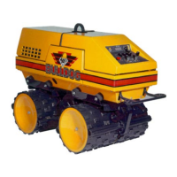
Bulldog
®
disengage the parking brake may cause damage to the
parking brake and/or to the machine.
ALWAYS fully apply the
parking brake when leaving the machine. Failure to
apply the parking brake could cause damage or
injury.
3.8 ENGINE SPEED/THROTTLE CONTROL
The engine speed is controlled through an electric
two-speed solenoid. Manipulation of the solenoid
will cause the engine to change between idle and run
speed.
3.8.1 Manual Mode (Item 6 Section 1.5)
This switch will cause the engine speed to change
from idle to run and vice versa. The Turtle Icon is
idle speed. The Rabbit Icon is run speed. For best
results start engine at idle speed. Always run
machine operations at run speed.
3.8.2 Remote Mode
Switching from engine idle to run speed is
accomplished automatically through the
microprocessor. When engine is started using the
transmitter, it will always start at idle speed. After
one second, it will automatically move to run speed.
3.9 MACHINE VEHICLE SPEED
Once the engine is at run speed, the vehicle speed is
controlled through the hydraulic valves which
manipulate pump flow. Switches control valve
operation.
3.9.1 Manual Mode (Item 5 Section 1.5)
This switch located on the control panel has three
functions:
1. High Travel Speed-Switch pushed fully
forward will give maximum vehicle speed
for travel. Note: Vibration is inoperative in
high speed.
2. Low Travel Speed-Switch pushed to the
center position will give slow speed with no
vibration. This speed is used for loading on
trailers or in trenches.
3. Vibe On-Switch pushed fully backward will
turn the vibration on. Machine will travel at
low speed with vibration.
3.9.2 Remote Mode (Item 6 Section 1.6)
This switch located on the transmitter has three
functions:
1. High Travel Speed-Button on the transmitter
pressed backward (towards Rabbit Icon) will
initiate high travel speed.
2. Low Travel Speed-Button on the transmitter
pressed forward (towards Turtle Icon) will
initiate low travel speed.
3. Vibe Off Button - pressing this button in
either high or low position will turn off
vibration if it has been activated.
3.10 DIRECTION AND STEERING CONTROL
This machines steering operates on a skid steering
type principle. Steering and directional control are
accomplished through the operation of switches that
actuate hydraulic valves thereby manipulating pump
flow.
3.10.1 Manual Mode (Items 7 and 8, Section 1.5)
Forward direction: Place the palm of your hands on
the control levers and move the levers to their
forward position (push). Machine motion will stop if
lever is released.
Reverse direction: Pull the control levers back by
grasping the knobs of the controls (pull). Machine
motion will stop if lever is released.
Turning is accomplished by counter-rotating the
drums. For example:
WARNING