- 28 -
3. OPERATION
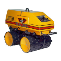
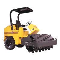
Bulldog
®
To make a left turn: Pull the left control lever down
to the reverse position while pushing the right control
lever up to the forward position.
To make a right turn: Push the left control lever up to
the forward position while pulling the right control
lever down to the reverse position.
3.10.2 Remote Mode (Items 4 and 5 Section 1.6)
Forward direction: Push buttons located on
transmitter down and forward in the direction
indicated by arrows. Buttons must be held down to
keep machine moving. Machine motion will stop if
button is released.
Reverse Direction: Push buttons located on
transmitter, down and backward in the direction
indicated by arrows. Buttons must be held down to
keep machine moving. Machine motion will stop if
button is released.
Turning is accomplished by counter-rotating the
drums. For example:
To make a left turn: Push the left control button down
to the reverse position while pushing the right control
button up to the forward position.
To make a right turn: Push the left control button up
to the forward position while pushing the right
control button down to the reverse position.
3.11 VIBRATION CONTROL
Machine vibration is accomplished by directing the
pump flow to the hydraulic motor on the eccentric
shaft. Manipulation of hydraulic valves determine
the vibratory mode and direction. Hydraulic valves
are switch-controlled.
3.11.1 Manual Mode (Items 4 and 5 Section 1.5)
To start vibration: Push switch (Item 5) fully
backward to initiate vibration on.
To stop vibration: Push switch (item 5) either fully
forward (high travel speed mode) or to center
position (low travel speed mode) to turn vibration
off.
Vibration forward direction: Push switch (item 4)
fully forward to rotate the eccentric shaft towards the
engine side of machine.
Vibration reverse direction: Push switch (Item 4)
fully backward to rotate the eccentric shaft towards
the operator side of machine.
3.11.2 Remote Mode (Items 6 and 7 Section 1.6)
To start vibration: Push switch (item 7) either
forward or reverse to initiate vibration on.
Note: This button does not have to be held on.
To stop vibration: Push switch (Item 6) either
forward (low travel speed) or reverse (high travel
speed) to turn vibration off.
Vibration forward direction: Push switch (Item 7)
towards the arrow pointing to the top of the
transmitter. This rotates the eccentric shaft towards
the engine side of the machine.
Vibration reverse direction: Push switch (Item 7)
towards the arrow pointing to the bottom of the
transmitter. This rotates the eccentric shaft towards
the operator side of the machine.
3.12 SAFETY ANTI-CRUSH BAR
3.12.1 Purpose And Location
A safety bar is mounted at the rear of the machine
below the operator panel. The purpose of the bar is
to stop reverse motion of the machine in the event
that an operator becomes entrapped behind it.
3.12.2 Operation
When the bar is depressed, it will open a switch.
This switch is located in the circuit that controls the
hydraulic valve operation giving reverse motion. If
the switch opens it will open the reverse motion