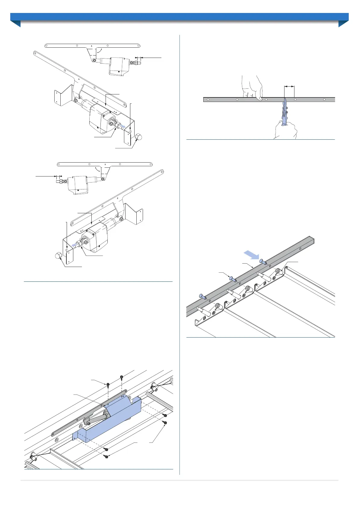
PREPARING LINK RODS
Lay the link rods on the ground, taking care not to bend them. The short angle should be
facing upwards. Determine where the link rod needs to be cut by counting the number
of holes required for the louvres. If the louvre bank is longer than 3m (14 louvres) a
second link rod will be required to make up the extra length. Mark and cut the link rod,
allowing 50mm overhang past the final hole (Figure 6.6).
If two link rods are required, for louvre banks over 3m (14 louvres), the link rods will need
to be joined using a Link rod joiner. Make sure to join the link rods at the uncut ends. Rivet
the link rod joiner to the link rod, through the 6 pre-drilled holes on the joiner.
Lift the link rods up and rest them along the mounting extrusion. Keep the rods straight
at all times when handling.
INSTALL LINK PINS
Connect both link rods, located at each end of the louvres, by pushing a link pin through the
appropriate hole in the link rod, and into the end cap (Figure 6.7). The link pins should push in
and snap fit into place for a solid hold. Repeat this process for the remaining louvres, ensuring
all louvres are orientated correctly and each lap is the same as the previous lap. Leave four
holes without pins where the drive arm will be fitted to the link rod.
If a link pin needs to be removed once it has been installed, squeeze the pin’s legs
together with needle nose pliers and push it towards the link rod until it releases.
CONNECT DRIVE ARM TO LINK ROD
Line the drive arm up with the four remaining link rod holes. Rotate the first free
louvre so the end cap hole is also aligned. Please note that the actuator may need to be
temporarily connected to the control box to move the drive arm to a suitable position
so the holes can be aligned.
Insert a bush through the drive arm and link rod, and into the first louvre end cap.
Similarly, insert another bush into the back of the end cap and secure with an M5 6x30
shoulder bolt and M5 lock-nut (Figure 6.8). The shoulder bolt head should be recessed
into the back of the end cap so that it is not visible. The M5 lock-nut will be located on
the drive arm side.
RUN CABLE TO CONTROL BOX
Note: The control box must be unplugged from the mains power.
Run the actuator connection cable from the actuator to the control box location. The
cable must be protected from the weather and sharp objects. The cable can be installed
so that it runs through the attachment beam, passing through the end of the beam and
fascia, eaves and finally to the control box location.
The actuator and cover are now ready to be fixed to the mounting extrusion.
INSTALL ACTUATOR AND COVER
Position the cover so the top lip hangs over the top of the internal ledge of the Beam
(Figure 6.5). The lip should be located centrally between the mounting bushes.
Note: The actuator can be located anywhere along the mounting extrusion, however,
it must be at least two louvres in from the ends and three louvres either side of a join
in the link rods.
Screw the top lip of the cover to the mounting extrusion with two 12x20 Self-Drilling
screws with Neoprene washers. Screw the front face of the cover to the mounting
extrusion with four 12x20 Self-Drilling screws with Neoprene washers (Figure 6.5).
12x20 self-drilling screws
12x20
self-drilling
screws
Locate lip centrally
between end cap bushes
Figure 6.5
Link Rod
Endcap
Link Pin
Figure 6.7
Circular cut-out with
the flat edge facing up
M16 nut
M16 dome nut
Actuator
cover
Thread nut
approx. 20mm
on to bolt
90°
Circular cut-out with
the flat edge facing up
M16 nut
M16 dome nutTYPE-A CONFIGURATION
TYPE-B CONFIGURATION
Actuator
cover
Thread nut
approx. 20mm
on to bolt
90°
Figure 6.4
10
50mm
Figure 6.6
 Loading...