LOUVRE INSTALLATION
Louvre Mounting Bushes must be fitted to the mounting beams prior to louvre
installation (Figure 2.0).
Determine the correct orientation for each louvre and prepare the ends accordingly.
Slide a spring bush into the end of each spring and thread over the end cap shaft.
Louvre orientation can be determined from the Allure plans provided.
At the opposite end of the louvre, slide a plastic spacer over the end cap shaft (use the
mark on the spacer to orientate it correctly) (Figure 6.0).
Please note that the actuator will always need to be located at the same end as the spacers.
Install the first louvre by lifting it up and over the beam at the spacer end. Insert the
other end (spring end) into the first hole and compress the spring completely (Figure
6.1). Lower the spacer end and slot it into the aligning hole (Figure 6.1).
ELECTRONIC CONTROL BOX
The control box must be installed in a position that is protected from direct weather
and sharp objects. The control box must not be installed within two metres of a large air-
conditioning unit or large sources of electrical noise. A suitable location may be to mount
the box against an exterior wall directly under the eaves. Alternatively, the box could be
located within the unit box gutter, alongside the actuator (see “Install Actuator Cover”).
Fix the control box through the four pilot holes on the cover box (Figure 6.2). If fixing
to an adjacent structure use fasteners suited to the material being fixed to. If fastening
within the box gutter use four 12x20 mm self-drilling screws.
A standard single mains power point is required to be located directly next to the
control box (within 1800 mm).
Lay the main cable on the ground from the control box position to the motor position
to ensure there is enough overall cable length. The kit has been supplied with a 6m
connection cable for both the actuator and rain sensor. If additional cable is required, an
extension cable can be purchased and used for up to 18m in length.
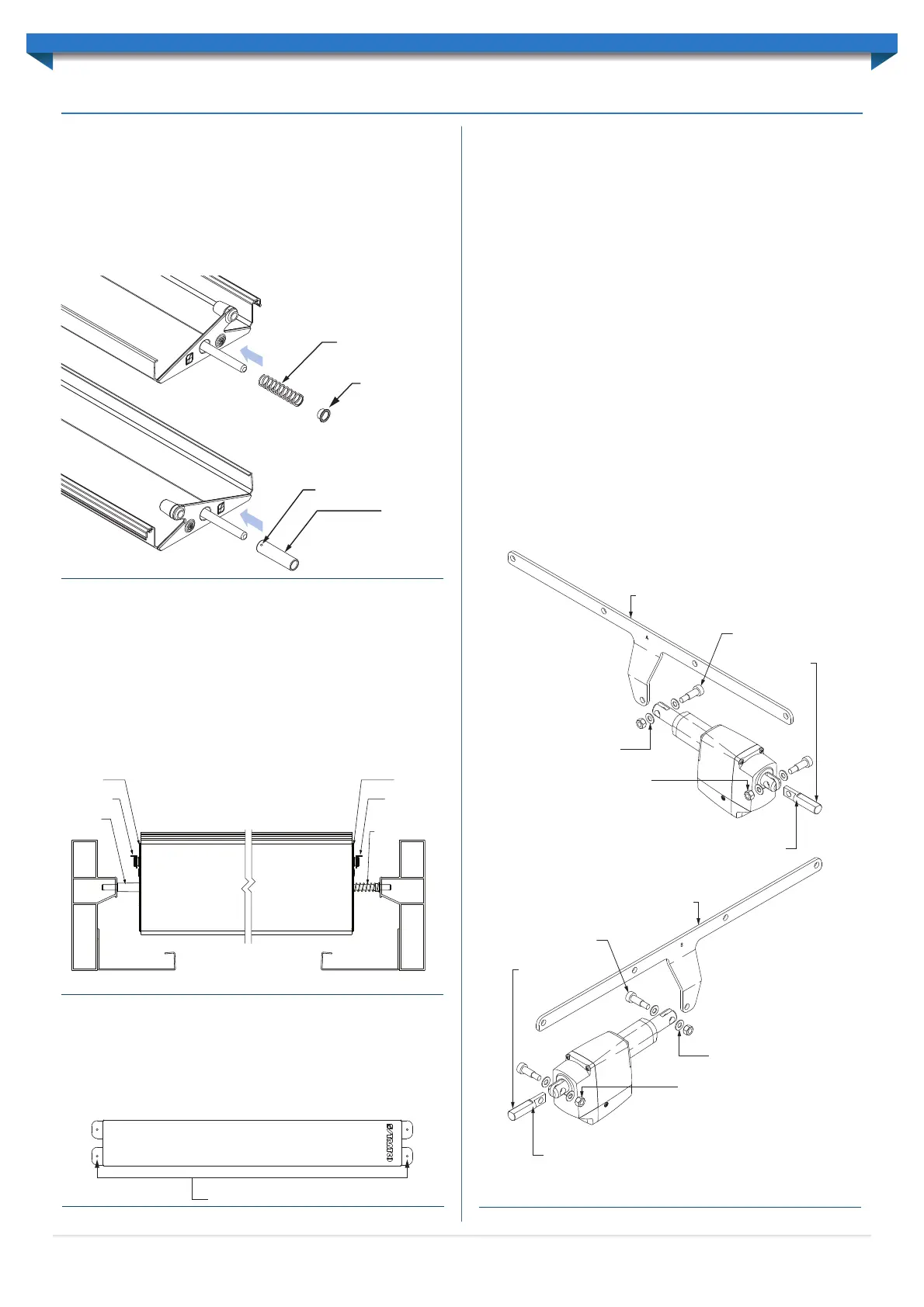
ASSEMBLE ACTUATOR COMPONENTS
Pre-assemble the actuator components at ground level. Attach the drive arm to the
actuator with an M8x10x20 shoulder bolt and secure with an M8 washer and lock-nut
(Figure 6.3). Please note that the drive arm should be orientated so the square edge
(with 90° angle) is facing the actuator.
Note: Sunroof systems will always operate with the actuator pulling the louvres open.
The location of the actuator in relation to the opening direction of the louvres will dictate
whether a Type-A or Type-B actuator kit is provided.
The appropriate orientation has been determined by Stratco, based on the opening
direction of the louvres relative to the intended motor location.
Attach the adjustment bolt to the other end of the actuator with an M8x10x20 shoulder
bolt (Figure 6.3). Secure with an M8 washer and lock-nut (do not over tighten the lock
nut). Ensure the flat surface on the adjustment bolt faces up.
Thread the M16 nut on to the end of the adjustment bolt so the nut is approximately
20mm in from the end of the adjustment bolt (Figure 6.3).
Insert the adjustment bolt through the circular cut out located in the side of the
actuator cover, and secure the cover with the M16 dome nut (Figure 6.4).
Spacer
Marking on spacer
Spring bush
Spring
Figure 6.0
Beam BeamGutter Gutter
Spacer
Link Rod Link Rod
Spring with
spring bush
Endcap Endcap
Figure 6.1
Fixing Pilot Holes (4x)
Figure 6.2
Drive arm
M8 10x20 shoulder bolt
M16 adjustment bolt
Flat edge facing up
M8 washer
M8 lock-nut
Drive arm
M8 10x20 shoulder bolt
M16 adjustment bolt
Flat edge facing up
M8 washer
M8 lock-nut
TYPE-A CONFIGURATION
TYPE-B CONFIGURATION
Figure 6.3
9
SUNROOF INSTALLATION
 Loading...