Drill a hole next to the actuator cover, ensuring it is above the gutter line. Use a 20mm
drill bit with 5mm pilot hole to drill through the front face of the extrusion and beam.
A wire pull through cable may be required to pull the cable through and out the end
of the beam.
Ensure the right end of the cable is threaded through the hole so it matches the control
box. The actuator connection cable has a 2 pin female end that connects with the 2 pin
male extension leading from the control box.
Rubber grommets have been supplied to protect the cable and must be installed at this
stage. Slit half way through the grommet so that it can be threaded over the cable and
into the hole.
Plug the 2 pin cable end into the control box and turn the power on.
USING THE REMOTE CONTROL
The remote control provided is used to control all Allure banks within the unit.
In units with multiple banks the two round buttons on the remote control are used to
select the appropriate bank channel. Channel one (1) is always used to control all banks
simultaneously. All other channels can be selected to operate banks individually.
Pressing the OPEN or CLOSE button will cause the roof to start moving in the desired
direction. The roof will continue until fully open or fully closed, or until the STOP button
is pressed. The stop button will stop the roof at any point.
ADJUSTING THE CLOSED POSITION
Use the remote control to drive the louvres until they are closed by pressing the ‘close’
button and allowing the unit to fully close.
Louvres Are Not Fully Closed
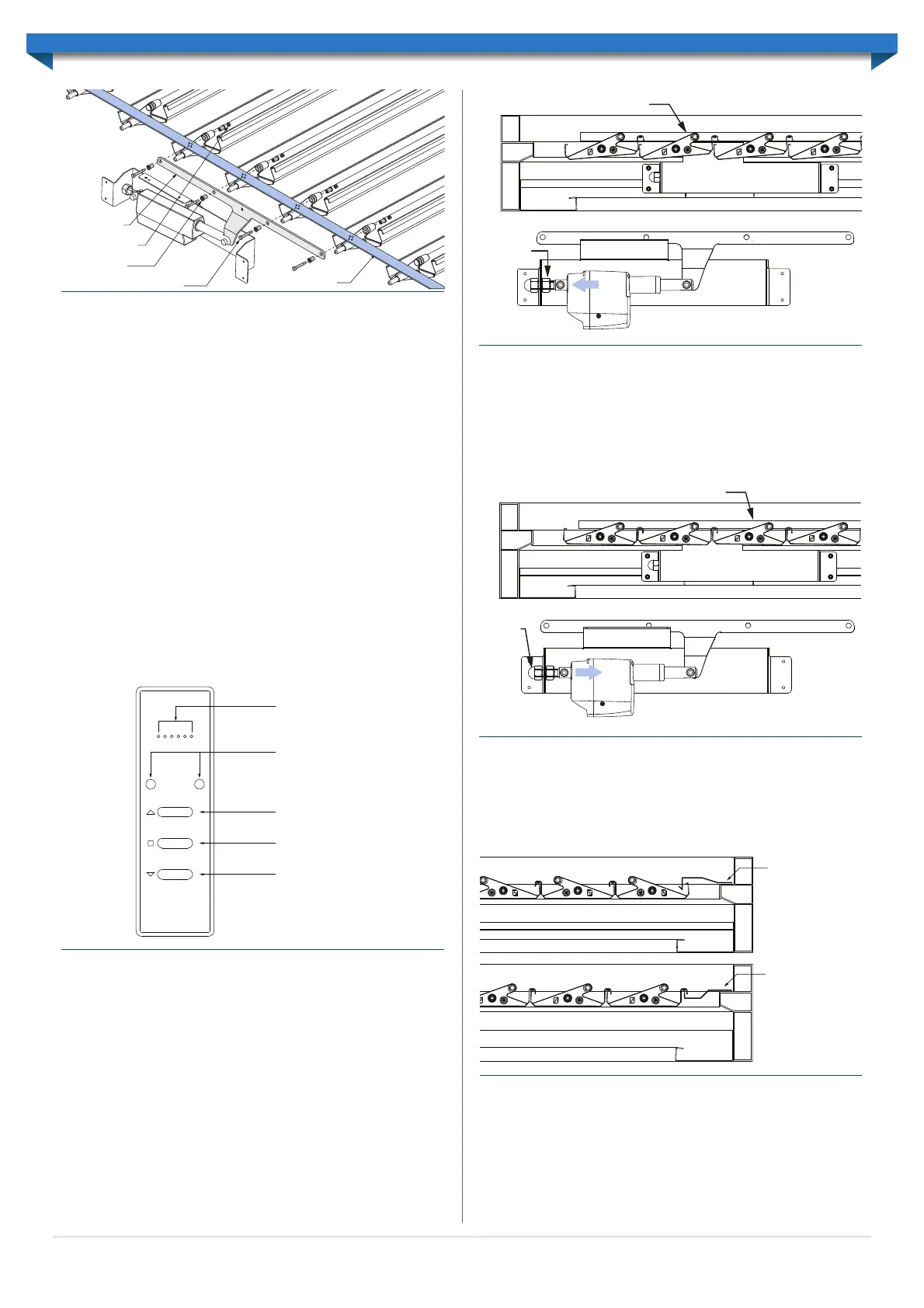
If the louvres have not closed fully, the position of the actuator must be adjusted.
Loosen the M16 nut by one to two rotations, and push the adjustment bolt away from the
actuator, through the circular cut-out in the side of the actuator cover. Tighten the dome
nut and use the remote control to open and close the louvres again (Figure 6.10). Repeat
this step until the louvres are fully closed, without deflecting the link rod.
Note: The louvres are in the fully closed position when the link rod becomes stiff (but
does not deflect) at the drive arm, ensuring it does not back drive the motor when the
‘closed’ button is released. If the actuator does back drive, this may reduce the systems life.
Louvres Are Closing Too Tightly
If the louvres have over closed, the link rod can be seen to significantly deflect.
To adjust the position of the actuator, loosen the M16 dome nut by one to two rotations,
and push the adjustment bolt towards the actuator, through the circular cut-out in the
side of the cover. Tighten the M16 nut and use the remote control to open and close
the louvres again (Figure 6.11).
Repeat this step until the louvres are fully closed, ensuring the link rod does not deflect.
INSTALLING COVER FLASHINGS
Fix the cover flashing to each end of the unit to eliminate any gaps when the louvres
are closed. Both flashings are designed to lap each end. Correct alignment is critical. The
flashings are fixed through the top of the beam with 12x20 Self-Drilling screws with
Neoprene washers at 900mm centres. Refer to Figure 6.12 for flashing layouts.
Where double-beams are used a double-beam cover flashing will need to be used to
cover the pilot holes created when joining beams together (Figure 2.13). The double-
beam cover flashing is placed over the double-beams and secured using 12x20 self-
drilling screws with neo washers along the length of the flashing (Figure 6.13).
Link rod flashings are installed along link rods with rivets at 500mm centres (Figure 6.14).
Link Rod
Drive Arm
M5 Lock Nut
Drive Bush
M5x6x30 Shoulder Bolt
Figure 6.8
Select bank
(left & right)
(multiple bank units only)
Open Louvres
Stop movement
Close Louvres
Bank Selection indicator
(multiple bank units only)
Figure 6.9
Louvres are not fully closed
Loosen
M16 nut
Move through
circular cut-out
Figure 6.10
Louvres are closed tightly with Link Rod deflecting
Loosen M16
dome nut
Move through
circular cut-out
Figure 6.11
Closing-up
cover flashing
Closing-down
cover flashing
Figure 6.12
11
 Loading...