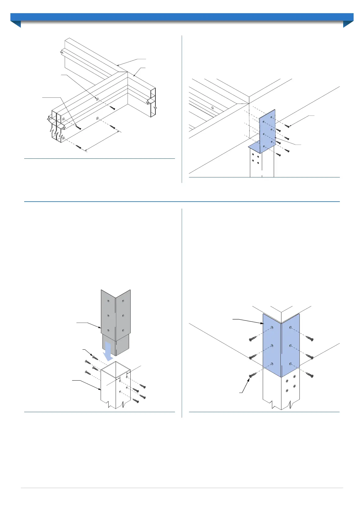
A ø10mm pilot hole must be made to allow fastening through the back-to-back
wall sections. These pilot holes are sealed with a cover flashing (see ‘Installing Cover
Flashings’).
10g x 30mm stainless
steel countersunk
screws
10mmø pilot hole
Bank 1
Bank 2
M
A
X. 600mm
C
ENT
R
ES
Note: Gutters omitted for clarity
Figure 2.13
Figure 2.14
10g x 30mm
stainless steel
countersunk
screws
Inline Post-to-Beam
Bracket
Bank 2
Bank 1
Note: All screws within the unit must be fastened by hand using a screw-driver, or a
low-torque, low-speed drill.
A post is connected using Inline Post-to-Beam brackets along the header beam where
back-to-back banks meet (Figure 2.14).
See ‘Post Installation’ for further post fixing details.
7
Figure 3.0
Post-Beam
Corner Bracket
10gx30 stainless steel
countersunk screws
Corner Post
3
0
mm
30
mm
Post-Beam
Corner Bracket
10gx30 stainless steel
countersunk screws
Figure 3.1
100x100 SHS Posts are used to support the Allure framework. Once the framework is
assembled and set at the correct pitch, the post height measurements must be taken.
Posts sit beneath the beams and can either be fixed into concrete footings or onto
concrete. Refer ‘Footing Installation’ for further details regarding Post fixing (see below).
Posts must be cut to the length determined from the framework height measurements
(refer ‘Footing Installation’).
Post-to-Beam Brackets must be fitted at the top of each post. Corner and Inline Post-
to-Beam brackets are supplied as determined by the design of the unit. Sit the Post-
to-Beam Bracket within the Post and drill ø3.5mm pilot holes centralised and 25mm
& 65mm down from the top of the Post on two opposing faces (Figure 3.0). These
holes must also be countersunk. Countersinks should have an outside diameter of
approximately 8mm to allow the screw head to sit flush.
Fix the Post-to-Beam Bracket to the post using 10gx30mm stainless steel countersunk
self-tapping screws (Figure 3.0).
Note: All screws within the unit must be fastened by hand using a screw-driver, or a
low-torque, low-speed drill.
Position posts at the required location beneath beams. Before fixing the Post-to-Beam
Brackets to the Framework the Posts must be measured plumb using a spirit level.
Drill pilot holes through to the Beam as per the locations determined on the Post-to-
Beam Bracket saddle. Fix the Post-to-Beam bracket to the Beam(s) using 10gx30mm
stainless steel countersunk self-tapping screws (Figure 3.1).
Note: All screws within the unit must be fastened by hand using a screw-driver, or a
low-torque, low-speed drill.
Inline Post-Beam bracket connections are fixed using the same process.
POST INSTALLATION
 Loading...