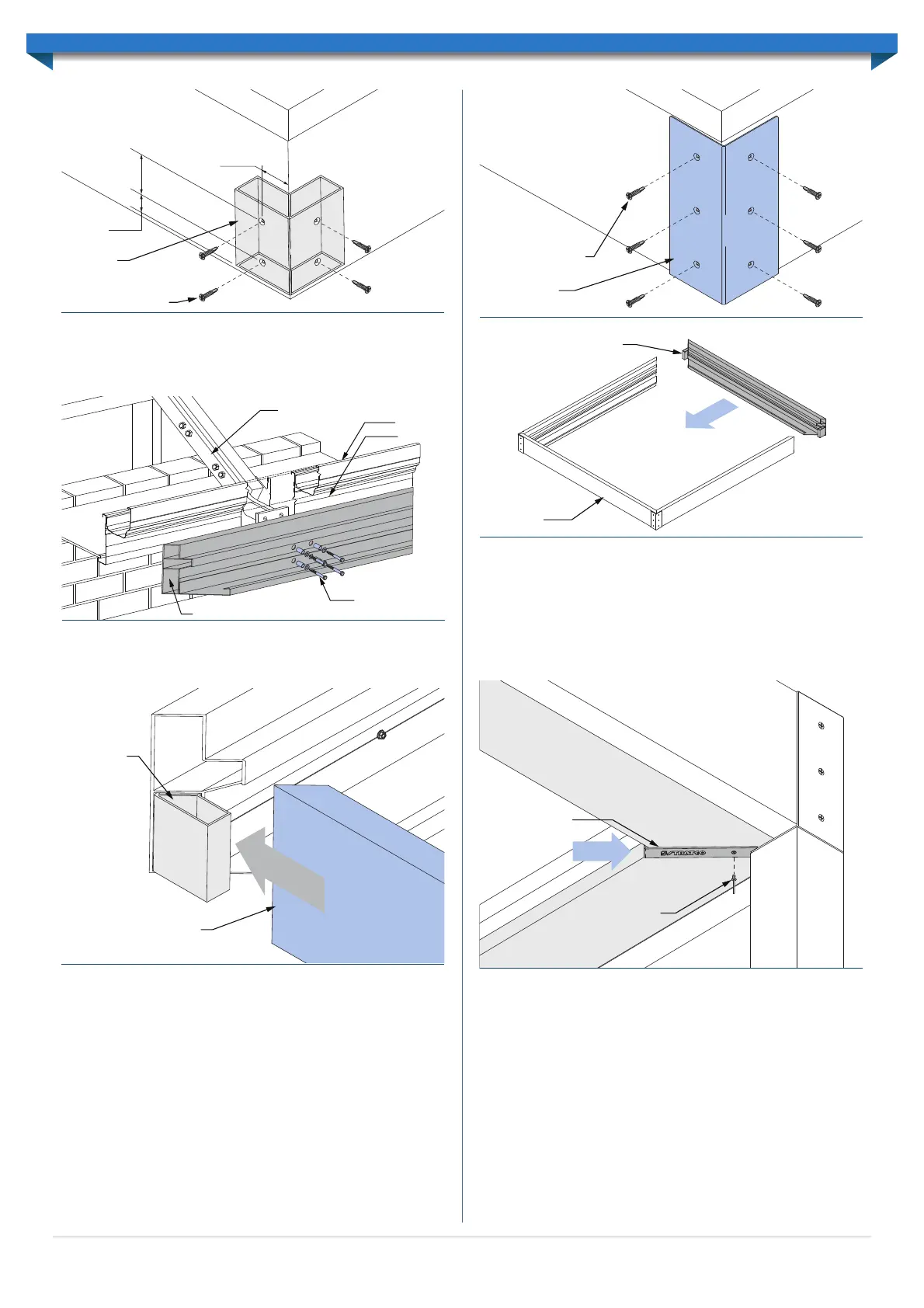
Fascia Beam Attachment
For units attached at the eaves, the Fascia beam is secured to the structure using Eaves
Fixing Brackets. Fix through the Eaves Fixing Brackets to the fascia beam using four M12
bolts with spacers and washers (Figure 2.8).
Side Beam Installation
The Side Beams must be propped in position at the required fall of 1° and over the pre-
installed Fascia Beam Corner Knuckle (Figure 2.9).
With the corner mitres aligned, ø3.2mm pilot holes must be drilled through the Side
Beams and the Corner Knuckles as per ‘Beam Preparation’. The pilot holes must also
be countersunk. Fasten the Side Beam to the Corner Knuckle using the 10gx30mm
stainless steel countersunk self-tapping screws provided (Figure 2.7).
Note: All screws within the unit must be fastened by hand using a screw-driver, or a
low-torque, low-speed drill.
Fascia Beam to Side Beam connections also require additional fastening using external
Corner Joiners. Corner Joiners must be fixed to the Fascia and Side Beams using
10gx30mm stainless steel countersunk self-tapping screws (Figure 2.10).
Once Side beams are attached the remaining Header Beam must be fixed using Corner
Knuckles as described in the previous paragraphs (Figure 2.11).
Gutter Straps
When the entire framework is erected each gutter mitre at corners can be concealed
using the Gutter Straps provided. Gutter Strap variations will be provided for corners
with posts (notched straps) and corners without (full-length straps). Slide the Gutter
Straps over the Mitres and drill a ø3.2mm pilot hole through the gutter. Fix the Gutter
strap to the Gutters using a 3.2mm rivet (Figure 2.12). If the rivet does not grip to
the gutters, a ø3mm washer may be required to sit inside the gutters to assist in fixing.
Internally seal each gutter mitre with silicone as required.
In the downpipe corner Gutter Straps will interfere with the downpipe. The interfering
gutter strap will need to be notched on-site to allow clearances. An angle grinder can be
used to trim the Gutter Strap to suit.
Multiple-Bank Frame Installation
In some instances a unit will feature multiple louvre banks. When this occurs separate
back-to-back banks are used with the banks fastened to one another. Louvres may run
parallel or perpendicular to the back-to-back beams.
When multiple banks are required all beams will be pre-mitred to facilitate installation
before going to site.
Where banks are adjacent to one another the back-to-Back beams are fixed together
using 10g x 30mm stainless steel countersunk self-tapping screws at a maximum spacing
of 600mm centres (Figure 2.13).
Gutter Strap
Rivet to gutter
Figure 2.12
Header Beam assembly
Fascia /
Attachment
Beam
Figure 2.11
Figure 2.9
Corner
Knuckle
Side Beam
10gx30 stainless steel
countersunk screws
Corner Joiner
Figure 2.10
Attachment Beam
Fascia
Gutter
Adjustable Rafter Strengthening Bracket
Four M12 Bolts with
spacers & washers
Figure 2.8
Corner
Knuckle
10g x 30mm stainless steel
countersunk screws
Fascia beam Side beam
60mm
30mm
50mm
Figure 2.7
6
 Loading...