Standard user guide
V51-00-V19 eng
-10- Rights to changes reserved
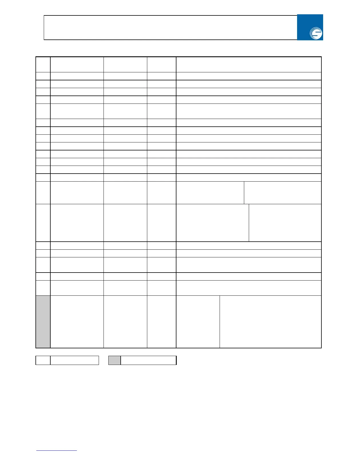
2.6 Parameter table – Standard frequency inverter (program 0)
Par
No:
Function: Range: Defaults: Description:
1 Max. Frequency 0,0 - 400 Hz 50,0 Hz Frequency at max analogue input = (10V or 20mA)
2 Min. Frequency 0,0 - 400 Hz 2,5 Hz Frequency at min analogue input = (0V or 0 / 4mA)
3 Acceleration 0,01 - 999 Hz/s 5,0 Hz/s Frequency increase in Hz per second
4 Deceleration 0,01 - 999 Hz/s 5,0 Hz/s Frequency decrease in Hz per second
5 V/F - curve 25 - 400 Hz 50,0 Hz Frequency at which the max output voltage is
obtained.
6 Boost 0,0 - 25% 5,0 % Additional output in % of max. voltage
7 DC – beak current 0,0 - 25% 0,0 % See section 2.7 for more information
8 DC – brake time 0,0 - 120 s 0,1 s See section 2.7 for more information
9 Start frequency 0,0 – 8,0 Hz 0,5 Hz See section 2.7 for more information
A Stop frequency 0,0 - 20,0 Hz 0,3 Hz See section 2.7 for more information
B Current limit 50 - 150% 150% See section 2.7 for more information
C TIP Frequency 0,0 - 400 Hz 10,0 Hz Frequency used for TIP mode and reference run
D Switch frequency 2,0 - 8,0 kHz 2,5 kHz See section 2.7 for more information
E Automatic restart
(Auto-Reset)
0 - 4 0 0: No Auto-Reset
1: Auto-R. after 1 sec.
2: Auto-R. after 10 sec
3: Auto-R. after 30 sec.
4: No Auto-Reset after
power up
F Display readout 0-200 0 0 : Output frequency
10: Motor current
20: DC link voltage
30: Position 3 most signif.
31: Position – With scroll
32: Position 3 least signif
33: Position only thousand
40: Slip (Hz)
50: Actual output
frequency
G Scale factor 0,001 - 1000 1,000 Scale factor for the readout value
H Relay function 0 – 99 0 See section 2.7 Par. H – Relay function page 15
J NPN – output /
DC - stop
0 - 120 101 See section 2.7 Par. J – Terminal 9 Function page 16
(max. load 200mA)
L Motor rev/min. 0-3.000 1.350 Motor rev / min at 50Hz
P Pulses pr.
revolution
00,1 – 1000,00 50,00 Set up the encoders pulse no pr. Rev.
0* Reference signal 1 - 8 1 1: 0-10V/
potmeter
2: 0-20 mA
3: 4-20 mA
5: 0-20 mA, where 0-10V has the
highest priority
6: 4-20 mA, where 0-10V has the
highest priority
7: Ramp generator
8: 0-10V Frequency input 2.
0-10V Voltage/Torque at input 3
X Not flashing
X* Normal flashing