Standard user guide
V51-00-V19 eng
-19- Rights to changes reserved
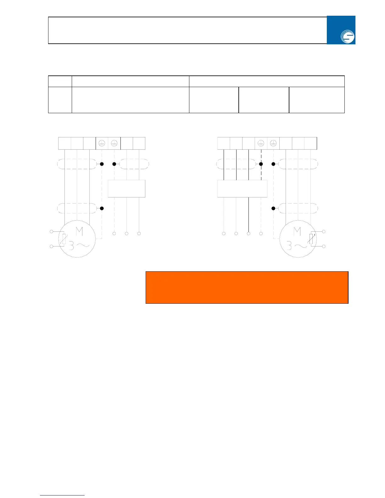
2.10 Mains supply
Net:
230 V ±10% / 50/60 Hz 3 x 400 V ±10% / 50/60 Hz
Type:
SC 750/5
SC 1500/5
SC3-1100/5
SC3-2200/5
SC3-4000/5
SC3-5500/5
SC3-7500/5
SC3-11000/5
SC3-22000/5
Important:
Following notes must be considered when planning and installing:
• The motor is protected by overheat by a PTC thermo sensor; witch can be connected on terminal 7, or
by a thermo regulator in the motor coils.
• Do not use a frequency dependent motor protection switch, use motor protection relay.
• If the motor wires are switched off at e.g. emergency stop, must the terminal 8 OFF input also be
switched off to avoid overload when restarted.
• Never connect mains supply at the output terminal U V W.
• Never use a “Megger” on the frequency inverter (Isolation test).
• Power up’s - unlimited.
• Install inverter after the EMC rules. See section 2.11
• Control wires must be separated from mains wires and motor wires.
WV
U
LN
N
L
PTC
Motor 3x230V
PE
L3
L2L1
L3
WV
U
Motor 3x400V
PTC
L2L1 PE
RFI
RFI
NOTE: When powering up the Speed Commander the display
shortly shows the software version, model no and program no. e.g.
5.0.0 - 0.75 - P2.