Standard user guide
V51-00-V19 eng
-20- Rights to changes reserved
Recommended length on motor cables. Use choke
coils if longer cable is needed.
Mains supply Motor wire length
1 x 230 V / 50/60 Hz Max. 30 m
3 x 400 V / 50/60 Hz Max. 15 m
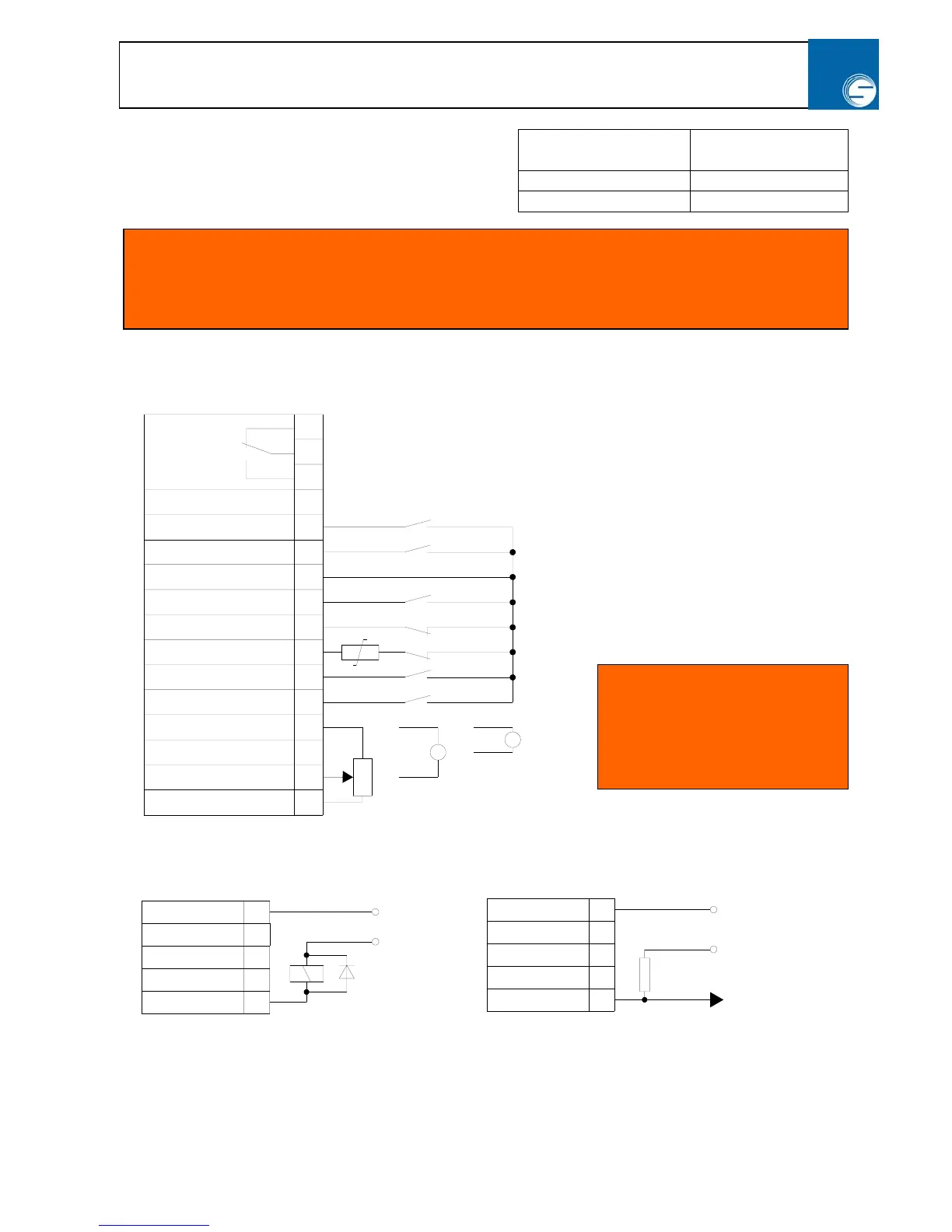
2.11 Control inputs
0(4)-20mA
10K
+10 VDC
0 V
+ 10 - 36V DC
- 0V DC
0-10VDC
11
9
10
12
13
1
2
+10 VDC
0 V
1W
11
9
10
12
13
12
7
6
3
4
5
10
11
8
9
=
=
15
16
13
14
- 0V DC
+ 10 - 36V DC
R = 1kΩ
NC
COM
NO
Motor potentiometer –
Motor potentiometer
+
+ 10 V DC as Term. 1
DC-Stop or NPN-out.
On / Off
STOP and PTC
Reverse
Forward
0 V
0(4)-20mA Speed.
0-10 VDC Speed.
+ 10 V DC as Term 10
0 V
Relay
max. load
1 A / 230 VAC
Indgangsimpedans for
styreindgange
2 : 85 kΩ
3 : 100 Ω / 85KΩ
5 : 20 kΩ
6 : 20 kΩ
7 : 20 kΩ
8 : 20 kΩ
9 : 85 kΩ
NPN – output:
a) Relay drive b) Inverted signal for e.g. PLC
to PLC
PN-output
Warning!
There can be a high voltage at the DC link capacitors in up to 5 min after mains disconnection.
Do not touch the motor wires and power connection.