9
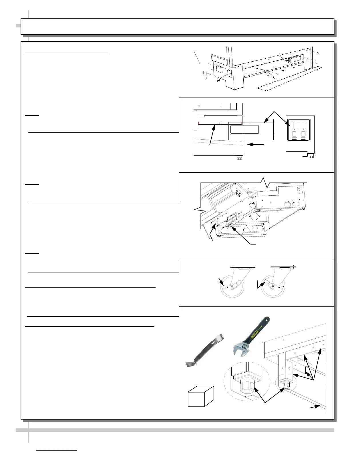
7. Electrical Connections
A. Rear Wire-Ways
Remove screws from rear wire-way cover to
access electrical leads.
Wiring runs case to case through base cut-outs.
Knockout is provided in bottom of wire-way for
stub-out connection.
See illustration at top-right.
Note: Wiring process must be performed by
certified electricians only.
Voltage rating is on serial label at case rear.
B. Rear Ballast Box
Remove 4 screws from ballast box face.
Remove screws from rear panel (if any).
Remove 3 screws from inner support.
Knockouts are located on side and rear of box
for making electrical connections.
Note
: Wiring process must be performed by
certified electricians only.
Serial label (at case rear) lists voltage rating.
C. Front Ballast Box
Remove front panel.
Stub-out connections are in ballast box.
Remove ballast box covers.
Knockouts are on sides and front of ballast
assembly for making electrical connections.
Note
: Wiring process must be performed by
certified electrician only.
Voltage rating is on serial label at case rear.
8. Cases With Casters: Lock and Unlock
To lock casters, press down on lever.
To unlock casters, pull lever up.
See illustration at right.
9. Cases With Levelers: Adjust Levelers
After case is in position, adjust case so it is level
and plumb (see illustration at right).
You may need to remove front and/or rear
Toe-Kick to access levelers.
Use adjustable wrench (and possibly a pry bar)
to adjust leveler.
Do not use pry bar on toe-kick (it may buckle).
Do not use pry bar on end panel (it may chip).
Use pry bar ONLY on base frame to avoid
damaging case.
Use a block to reach base frames with pry bar.
See illustrations at right.
Front Ballast
Box Covers
Electrical Leads
Access
Raceway
Cover
Ballast
Wireway
Ballast Box
Inner Support
Case
Rear
Case Rear
Side View
INSTALLATION: ELECTRICAL CONNECTIONS / LOCKING CASTERS / ADJUSTING LEVELERS
Pry Bar
Base
Frame
Leveler
Adjustable
Wrench
Toe-Kick
Block
Loc
k
ed
U
n
l
o
c
k
e
d