14 www.stryker.com
EN 0703-001-700 Rev-C
6 Features
6.1 Hardware Interface
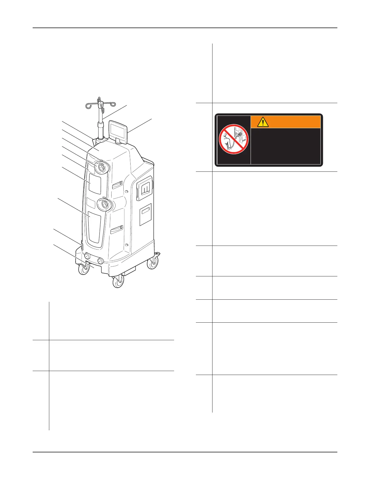
6.1.1 Rover Front View
C
B
A
J
D
E
F
G
H
K
I
Figure 8 – Rover Front View
A Docking Station Interface (not shown) –
Provides a sealed flow path for fluid waste
transfer from the rover to the docker. Also
provides fresh water and detergent transfer from
the docker to the rover canisters.
B Infrared Communication Window – Allows data
transfer between the docker and rover during the
docking procedure. See Section 17 Glossary for
the definition of infrared communication.
C 20L (20-liter) Canister – Allows for the collection
and containment of fluid waste. The 20-liter
canister receives fluid through an installed
manifold during collection. The canister contains
a fluid level sensor to provide volume information
to the top and main displays. See Section 8.3.1.3
To Manage a Full Canister. See Section 17
Glossary for the definition of a fluid level sensor.
D 4L (4-liter) Canister – Allows for the collection
and containment of fluid waste. The 4-liter
canister receives fluid through an installed
manifold during collection. The canister contains
a fluid level sensor to provide volume information
to the top and main displays. The contents of the
4-liter canister may be emptied into the 20-liter
canister.
E High Suction Device WARNING Label (two) -
WARNING
HIGH SUCTION DEVICE
DO NOT connect directly to
chest tubes or other closed
wound drains.
Failure to comply could result
in serious injury or death.
F Manifold Receptacle (two) – Allows installation
of a disposable manifold into the canister. The
installation or removal of a valid manifold enables
or disables suction, respectively. See Section
17 Glossary for the definitions of a valid and
invalid manifold. The receptacle port will close
automatically when a manifold is removed.
Closure prevents fluid waste leakage from the
canister and prevents foreign objects from
entering the canister.
G Suction Range Indicator (two) – Provides color-
coded visual information about the suction limit
range. See Table 5 Suction Limit Ranges and
Colors.
H Speaker – Located inside the rover; provides
audible event indicators. See Table 11 Audible
Event Indicators.
I Quick Reference Card (QRC) – Allows for
quick access to warnings and troubleshooting
information.
J Height Adjustable, Powered IV Pole with Four
Hooks – This IV pole is capable of supporting
one three-liter [3000 mL] fluid bag per hook.
The powered IV pole will return to its lowest
position automatically when power is removed
from the rover, to ensure proper clearance during
relocation.
K Top Display – Provides visual information of
status, as well as safety and alarm indications
(Figure 10 and Figure 17). The display swivels
in a 360-degree fashion and pivots for ease of
viewing from the surgical field or control panel.
0000160552, Rev. C Effective Date: Nov 25, 2015 1:43:15 PM
Print Date: Nov 25, 2015 02:19:13 PM
 Loading...