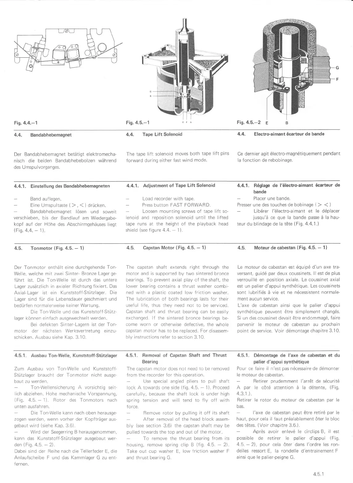
Fig.4.4.-1
Fis.
4.5.-1
Fi1.4.5.-2
E
4.4.
Bandabhebemagnet
Der Bandabhebemagnet
betätigt
elektromecha-
nisch die beiden
Bandabhebebolzen während
des Umspulvorganges.
4.4.
Tape Lift Solenoid
The tape
li{t solenoid
moves
both
tape
lift
pins
forward
during
either
fast wind
mode.
4.4. Electro-aimant 6carteur de bande
Ce
dernier agit 6lectro-magn6tiquement
pendanl
la fonction de rebobinage.
4.4.1. Einstellung
des Bandabhebemagneten
Band auflegen.
Eine Umspultaste
(
),
(
)
drücken.
Bandabhebemagnet lösen
und soweit
verschieben,
bis der Bandlauf am Wiedergabe-
kopf
auf der Höhe
des
Abschirmgehäuses
liegt
(Fis.
4.4.
-
1).
4.4.1.
Adjustment
of Tape Lift
Solenoid
Load
recorder
with tape.
Press
button FAST FORWARD.
Loosen mounting screws of tape lift so-
lenoid
and
reposition
solenoid
until the lifted
tape runs at the height of the
playback
head
shield
(see
figure 4.4.
-
1).
4.4.1. R6glage
de
l'6lectro-aimant
6carteur
de
bande
Placer une bande.
Presser une des touches de bobinage
(
)
(
)
Lib6rer l'6lectro-aimant et
le döplacer
jusqu'ä
ce
que
la bande
passe
ä la hau-
teur du blindage de la t6te
(Fig.
4.4.1.)
4.5. Tonmotor
(Fig.
a.5.
-
1)
Der Tonmotor enthält
eine durchgehende
Ton-
Welle, welche mit
zwei Sinter-
Bronze Lager
ge'
führt
ist. Die
Ton-Welle
ist durch das
untere
Lager
zusätzlich in axialer Richtung
fixiert. Das
Axial-Lager ist ein Kunststoff-Stützlager.
Die
Lager sind
für die Lebensdauer
geschmiert
und
bedürfen
normalerweise keiner
Wartung"
Die Ton-Welle und das
Kunststoff-Stütz-
lager können einfach ausgewechselt werden.
Bei defekten Sinter-Lagern
ist
der
Ton-
motor der nächsten Werksvertretung
ei nzu-
schicken. Ausbau siehe Kap.3.10.
4.5. Capstan Motor
(Fig.4.5.
-
1)
The capstan shaft
extends right through
the
motor and is supported by two sintered bronce
bearings. To
prevent
axial
play
of the shaft, the
lower
bearlng contains a thrust washer combi'
ned with a
plastic
coated
low friction
washer.
The lubrication
of both bearings lasts for their
useful life, thus
they need not to be serviced.
Capstan
shaft
and thrust bearing can be
easily
exchanged. lf
the sintered bronce bearings
be-
come worn
or otherwise defective, the
whole
capstan motor has
to be replaced. For
disassem-
bly instructions
refer to section 3.,1 0.
4.5. Moteur de cabestan
(Fig.
4.5.
-
1)
Le moteur de cabestan est dquipd dlun
axe tra-
versant,
guidd
par
deux coussinets.
ll est de
plus
verrouillö
en
position
axiale. Le coussinet
axial
est un
palier
d'appui synth6tique.
Les coussinets
sont lubrifids ä vie et
ne ndcessistent normale-
ment aucun service.
L'axe de cabestan
ainsi
que
le
palier
d'appui
synth6tique
peuvent
ötre simplement changÖs.
Si un des
coussinet
devait 6tre endommag6,
faire
parvenir
le moteur de cabestan au
prochain
point
de
service.
Voir
d6montage chapitre
3.i 0.
4.5.1.
Ausbau Ton-Welle,
Kunststoff-Stützlager
Zu
m Ausbau
von Ton-Welle und Kunststof f-
Stützlager braucht der Tonmotor nicht ausge-
baut zu werden.
Ton-Wellensicherung A vorsichtig
seit-
lich abziehen. Hohe mechanische Vorspannung,
(Fig.
4.5.
-
1). Rotor des Tonmotors nach
unten
ausfahren.
Die Ton-Weile kann nach oben herausge-
zogen werden, wenn vorher der Kopfträger aus-
gebaut
wird
(siehe
Kap. 3.6).
Wird der Seegerring
B herausgenommen,
kann das Kunststoff-Stützlager ausgebaut wer-
den
(Fig.
4.5.
-
2).
Dabei sind der Reihe nach die Tellerfeder E, die
Anlaufscheibe
F und das
Kammlager
G
zu ent-
fernen.
4.5.1. Removal
of Capstan
Shaft
and Thrust
Bearing
The capstan motor does not need
to
be
removed
lrom
Lhe
recorder
{or this
operation.
Use special angled
pliers
to
pull
shaft
lock A towards one side
(fig.4.5.
-
1). Proceed
carefully,
because the shaft lock
is
under high
spring
tension and will tend to
f ly
off
with
force.
Remove rolor by
pulling
it off its
shaft
After
removal
of
the head block assem-
bly
(see
section 3.6)
the capstan shaft may be
pulled
towards the top and out of
the motor.
To remove the thrust bearing
from its
housing,
remove spring clip B
(fig.
4.5.
-
2).
Take
out
cup washer E, low
friction
washer F
and
thrust bearing
G.
4.5.1.
D6montage de
I'axe de cabestan et du
palier
d'appui synth6tique
Pour
ce faire il n'est
pas
n6cessaire de ddmonter
le
moteur de cabestan.
Retirer
prudemment
l'arr6t
de
sdcuritd
A
par
le
cöt6 attention
ä la ddtente,
(Fig.
4.3.1.).
Retirer
le rotor du moteur de cabestan
par
le
bas.
l'axe de cabestan
peut
Ötre
retird
par
le
haut,
pour
cela il faut
pr6alablement
öter le bloc
des tötes.
(Voir
chapitre 3.6.).
Aprös
avoir enlevd
le iirclips B, il est
possible
de retirer le
palier
d'appui
(
Fig.
45.
-
21
,
pour
cela
öter dans
l'ordre les ron-
deiles
ressort E, la rondelle
d'entrainement
F
ainsi
que
le
palier-peigne
G.
4.5.1
 Loading...