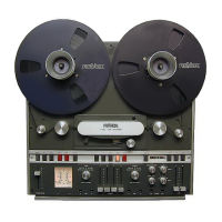
Fig.5.2=2
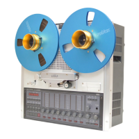
Fis. 5.2-3
Tonbandmaschine auf
Wiedergabe star-
ten.
Linke
Bandzugwaage: Potentiometer
R 3
(Fig.
5.2.
-
2l so verstellen bis der Abstand
a1 von
Oberkante
der Tastenschiene bis zum
Fühlerarm 46 mm beträgt.
Rechte Bandzugwaage: Potentiometer
R 3
(Fig.
5.2.
-
3l so
verstellen
bis der
Abstand
a2 von
Oberkante
der
Tastenschien bis zum
Fühlerarm 50 mm beträgt.
Kann
diese
Einstellung nicht erfüllt werden, so
muss auf dem linken Abtasterprint
(1.067.190)
bzw.
dem
rechten Abtasterprint
(1.067.210),
der Widerstand R 5 von
4.1 k
auf
10 k
erhöht
werden.
Start recorder
in the
PLAY mode.
Left-hand tape
tension
sensor: Ad.just
potenriometer
R
3
(fig.
5.2.
-
2l to obtain
a
position
of the
guide
roller so
that
distance
"a1"
equals 46 mm.
Right-hand
tape tension sensor:
Adjust
potentiometer
R 3
(fiS.
5.2.
-
3l
to
obtain
a
position
of the
guide
roller so
that distance
"a2"
equals 50
mm.
lf the specified
positions
cannot
be obtained in
this way,
resistor R 5 in the
tape tension sensor
circuits
'l
.067.190 and
1.067.210
respectively
have
to be increased
from
4,7 kOhm to
10
kOhm
Presser la touche de
lecture.
Palpeur
gauche:
rdgler le
potentiomÖtre
R 3
(Fig.
5.2.
-
2\
jusqu'ä
l'obtention
d'un
6cart
de
46
mm.
Entre la
.partie
sup6rieure
du
rail de
guidage
des
touches et
le
palpeur.
Palpeur droit:
r6gler le
potentiomÖtre
R 3
(Fig.
5.2.
-
3l
jusqu'ä
l'obtention d'un
6cart de 50 mm.
Entre la
partie
supdrieure du
rail
de
guidage
des
touches et le
palpeur.
Au cas
oü
il ne serait
pas posible
d'obtenir ce
169lage, il faudrait alors modifier
la valeur de
R 5 de 4.7 k ä 10k sur les
prints
de
gauche
(1.067.190)
et droit
(1.067.210).
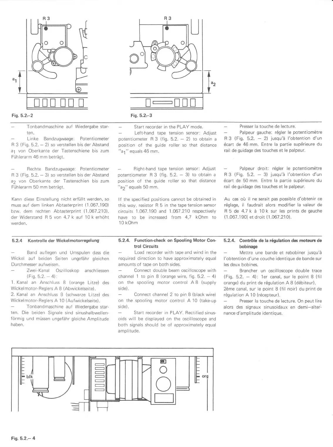
5.2.4 Kontrolle
der Wickelmotorregelung
Band auflegen
und Umspulen
dass die
Wickel
auf beiden Seiten ungefähr
gleichen
Durch
messer aufweisen.
Zwei-Kanal
Oszilloskop
anschliessen
(Fig.5.2.
-
4l
1. Kanal
an Anschluss
B
(orange
Litze)
des
Wickelmotor-Reglers
A B
(Abwickelseite).
2.
Kanal an Anschluss
B
(schwarze
Litze) des
Wickelmotor-Reglers
A 10
(Aufwickelseite).
Tonbandmaschine
auf Wiedergabe
star-
ten. Die
beiden
Signale sind sinushalbwellen-
förmig
und müssen
ungefähr
gleiche
Amplitude
haben.
5.2.4.
Function-check on Spooling Motor Con-
trol Circuits
Load recorder
with
tape and wind in the
required direction to have approximately equal
amounts of tape
on both sides.
Connect double beam oscilloscope
with
channel
1
to
pin
B
(orange
wire, fig. 5.2.
-
4l
on the spooling motor control A B
(supply
side).
Connect
channel 2 to
pin
B
(black
wire)
on the spooling
motor control
A
10
(take-up
side).
Start recorder
in PLAY. Rectif ied
sinus-
oids
will
be
displayed on the oscilloscope
and
both signals should be of approximately
equal
amplitude.
5.2.4.
Contröle de la r6gulation des
moteurs de
bobinage
Mettre une bande
et
rebobiner
jusqu'ä
l'obtention
d'une couche identique de bande
sur
les
deux bobines.
Brancher un oscilloscope
double trace
(Fig.
5.2.
-
4l:
1er canal, sur
le
point
B
(fil
orange) du
print
de rdgulation A B
(ddbiteur),
2öme
canal, sur
le
point
B
(f
il noir) du
print
de
rdgulation A 10
(rdcepteur).
Presser
la touche de Iecture. On
peut
lire
alors
des signaux sinusoidaux en demi-altei:
nance
d'amplitude identique.
E]
o
o
Fis. 5.2.-
4
 Loading...