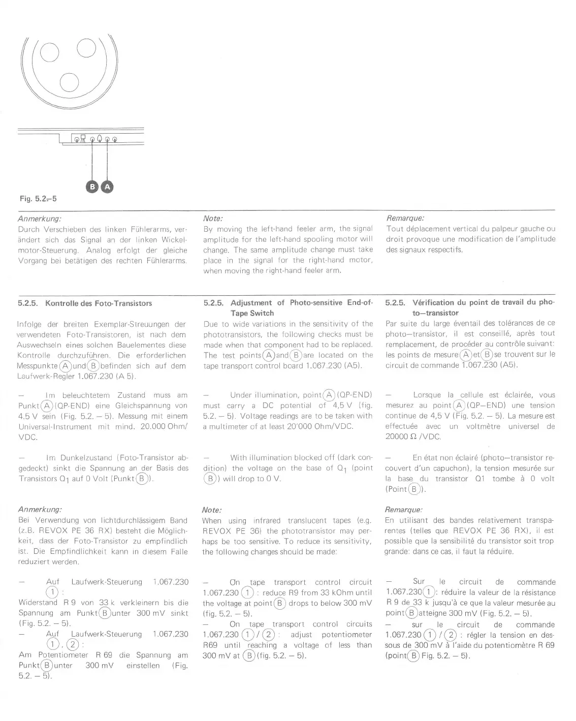
Fig.
5.2-5
Anmerkung:
Durch Verschieben des linken Fühlerarms, ver-
ändert sich
das Signal an der
linken Wickel-
motor-Steuerung. Analog erfolgt der
gleiche
Vorgang
bei betätigen des rechten
Fühlerarms.
Note:
By moving the
left-hand feeler
arm, the
signal
amplitude
for the
left-hand spooling
motor
will
change. The
same amplitude
change must
take
place
in
the signal
for the right-hand
motor,
when moving
the right-hand
feeler arm.
Remarque:
Tout d6placement
vertical
du
palpeur gauche
ou
droit
provoque
une
modif ication de l'amplitude
des
signaux
respectifs.
5.2.5. Kontrolle
des Foto-Transistors
lnfolge der breiten Exemplar-Streuungen der
verwendeten
Foto-Transistoren, ist
nach
dem
Auswechseln eines solchen Bauelementes diese
Kontrolle
durchzuführen. Die erforderlichen
Messpunkte@und@OefinOen
sich auf dem
Laufwerk-Regler 1.067.230
(A
5).
lm
beleuchtetem
Zustand
muss am
Punkt@{OP-END)
eine Gleichspannung
von
4.5
V sein
(Fig.
5.2.
-
5).
Messung mit einem
Universal-lnstrument
mit mind.
20.000 Ohm/
VDC"
lm Dunkelzustand
(Foto-Transistor
ab-
gedeckr)
sinkt die Spannung an der
Basis
des
Jransistors O1
aul
0 Volt
(Punkt(B)).
Anmerkung:
Bei Verwendung
von lichtdurchlässigem
Band
(2.8.
REVOX PE
36 RX) besteht
die
Möglich-
keit,
dass der
Foto-Transistor zu empfindlich
ist.
Die Empf
indlichkeit kann in
diesem Falle
reduziert
werden.
Auf
Laufwerk-Steuerung 1 .061 .230
o,
Widerstand
R 9 von 33 k
verkleinern bis die
Spannung
am Punkt@unter 300 mV sinkt
Itri^ Ra Är
at,
AUf
Laufwerk-Steuerung 1.061
.230
o,@,
Am Potentiometer
R
69 die Spannung am
Punkt@unter
300 mV einstellen
(fig.
5.2.
-
51.
5.2.5. Adjustment
of
Photo-sensitive End-of-
Tape Switch
Due to wide
variations
in the sensitivity of
the
phototranslstors,
the following
checks must
be
made when that
component had to be
replaced.
The test
points(A)and@are located on the
tape transport control
board 1.067.230
(A5).
-
Underillumination,ooint@(oP-END)
must carry a
DC
potential
of
4,5 V
(f
ig.
5.2.
-
5\.
Voltage readings are to be
taken with
a multimeter of at least 20'000 Ohm/VDC.
With illumination blocked
off
(dark
con-
{{on)
the
voltage on
lhe base ol 01
(Doint
(B))
willdrop
to 0 V.
Note:
When
using
infrared translucent
tapes
(e.9.
REVOX
PE 36)
the
phototransisLor
mdy
per-
haps
be
too sensitive. To reduce
its sensitivity,
the
following changes
should be made:
-
On
^tape
transport conLrol circuiL
1.061
.23O (f
: reOuce R9 f rom 33 kohm until
Lhe voltage aL
point(B)
drops
to below 300 mV
(fis.
5.2.
*
5).
on
tape transport control circuits
1.061
.230
4
t
@.
adjust
potentiometer
R69 until reaching a
voltage of less
than
3oO mV ar
@(fis.
5.2.
-
5).
5.2.5. V6rification
du
point
de travail
du
pho'
to-transistor
Par suite
du large 6ventail
des tol6rances
de ce
photo-transistor,
il est conseill6,
aprÖs
tout
remplacement,
de
proc6der
au contrÖle
suivant:
les
points
de mesure(Ä)et@se
trouventsur
le
circuit de
commande
1.067.230
(Ab).
Lorsque la
cellule est 6clair6e,
vous
mesurez
au
point@(OP-END)
une tension
continue
de 4,5 V
(Fig.
5.2.
-
5).
La
mesure est
effectu6e
avec un voltmötre
universel de
20000
a /vDC
En 6tat non 6clai16
(photo-transistor
re-
couvert d'un capuchon), la tension
mesur6e
sur
la base du transistor
01 tombe ä
0 volt
(noint@).
Remarque:
En
utilisant des bandes
relativement transpa-
rentes
(telles
que
REVOX PE 36 RX),
il
est
possible que
la sensibilitö
du
transistor soit trop
grande:
dans ce cas, il faut la rdduire.
Sur
le
circuit
de
commande
1.067.230@:
rdduire
la valeur
de
la
rdsisrance
R
9 de 33 k
jusqu'ä
ce
que
la valeur
mesur6e
au
poinL(e)atteigne
300
mV
(Fis.
5.2.
-
b).
sur le circuit
de commande
1.061
.230
@
t
@
:
r6gler la tension en des-
sous
de 300 mV ä l'aide du
potentiomötre
R 69
(point@
Fig.
b.2.
-
5).
 Loading...