lxllln
!!r!!
[
T
m
"."TTII
"'"
äF
II
Fis.
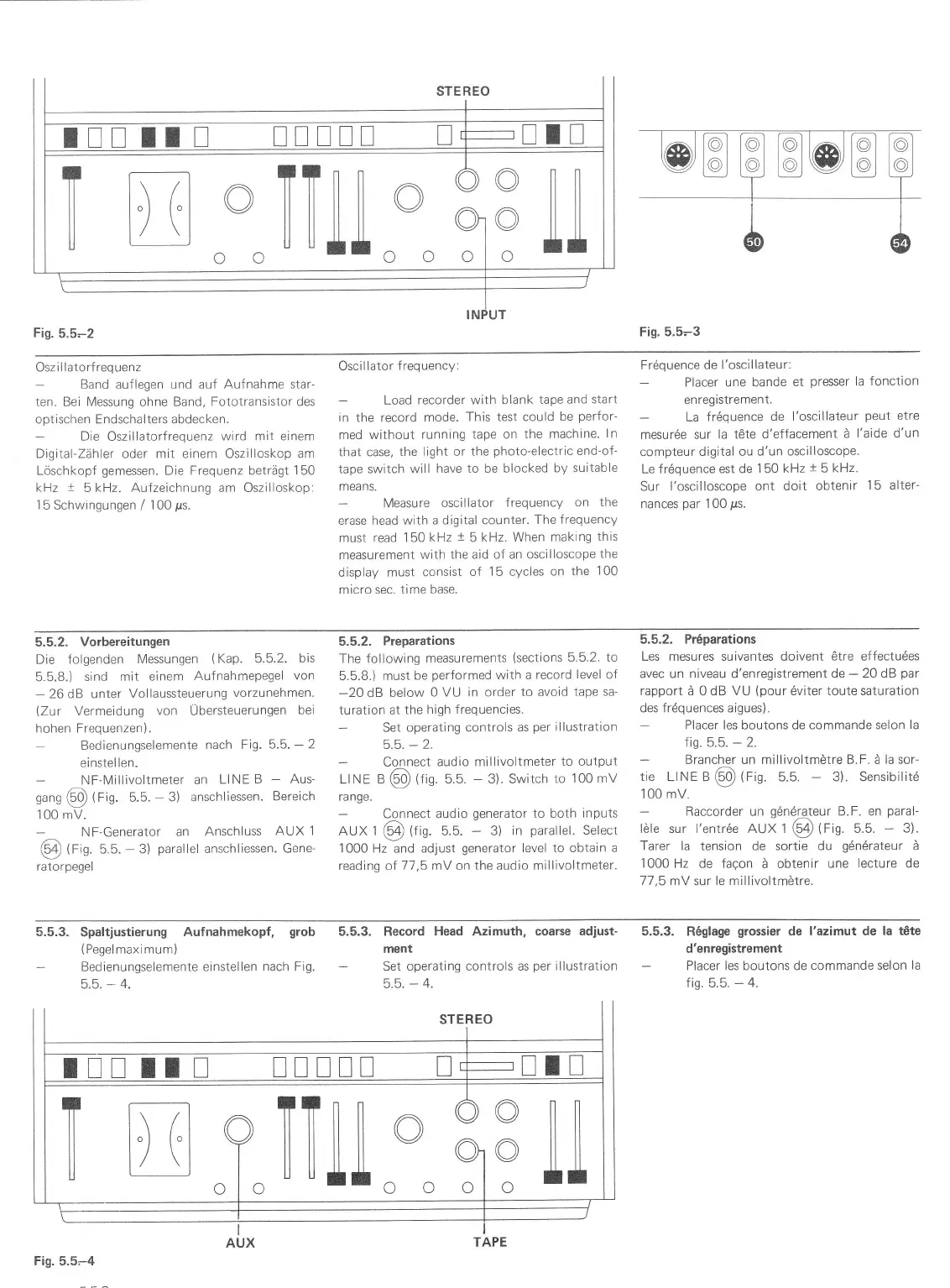
5.5-2
Fig. 5.5-3
Oszillatorfrequenz
Band
auflegen und auf
Aufnahme star-
ten. Bei Messung
ohne
Band, Fototransistor des
optischen Endschalters abdecken.
-
Die
Oszillatorfrequenz
wird mit einem
Digital-Zähler oder mit einem Oszilloskop am
Löschkopf
gemessen.
Die
Frequenz
beträgt
150
kHz
1
5 kHz. Aufzeichnung am Oszilloskop:
1
5 Schwingungen
/
100
ps.
Oscillator
frequency:
Load
recorder with blank
tape and
start
in the record
mode.
This test could
be
perfor-
med
without running
tape on
the machine.
ln
that case,
the light or
the
photo-electric
end-of-
tape switch will
have to be blocked
by
suitable
means.
Measure
oscillator frequency
on the
erase head with
a digital counter.
The frequency
must read
'1
50
kHz
1
5
kHz. When
making
this
measurement
with
the aid of an oscilloscope
the
display
must consist
of
15
cycles
on
the 100
micro sec. time base.
Frdquence de
l'oscillateur:
Placer une bande
et
presser
la fonction
en
registrement.
La
frdquence
de l'oscillateur
peut
etre
mesur6e sur
la töte d'effacement
ä
l'aide d'un
compteur digital ou
d'un oscilloscope.
Le fr6quence
est de
1
50
kHz
t
5
kHz.
Sur l'oscilloscope
ont
doit obtenir
15 alter-
nances
par
1 00
ps.
5.5.2.
Vorbereitungen
Die folgenden
Messungen
(Kap.
5.5.2.
bis
5.5.8.)
sind mit
einem
Aufnahmepegel
von
-
26dB unler Vollaussteuerung
vorzunehmen.
(Zur
Vermeidung
von
Übersteuerungen
bei
hohen Frequenzen).
Bedienungselemente
nach Fig.
5.5.
-
2
einstel
len.
NF-Millivoltmeter an
Ll NE
B
-
Aus-
sans
@
(Fig.
5.5.
-
3)
anschliessen.
Bereich
100 mV.
N
F-Generator
an
Anschluss
AUX 1
@
tfig.
5.5.
-
3)
parallel
anschliessen.
Gene-
ratorpegel
5.5.2.
Preparations
The following measurements
(sections
5.5.2.
to
5-5.8.)
must
be
performed
with a
record level of
-20
dB
below
0 VU in order
to avoid
tape sa-
turation at
the
high frequencies.
Set
operating controls
as
per
illustration
Connect
audio millivoltmeter
to output
Lt NE B
@
lt'n.
5.5.
-
3). Switch
to
100
mV
range.
Connect audio
generator
to both
inpuls
AUX
1
€4
(fig.
5.5.
-
3)
in
parallel.
Select
1000 Hz and adjust
generator
level to obtain
a
reading of 17
,5
mY on
the audio millivoltmeter.
5.5,2,
Pr6parations
Les mesures suivantes doivent ötre effectudes
avec un niveau d'enregistrement de
-
20 dB
par
rapport
ä 0 dB
VU
(pour
6viter toute saturation
des f r6quences aigues).
Placer les boutons de commande selon
la
fis. 5.5.
-
2.
Brancher un millivoltmötre B.F. ä
la
sor-
tie
LINE e
@
tris.
5.5.
-
3). Sensibilitd
100
mV.
-
Raccorder un
göndrateur
B.F. en
paral-
löle
sur
l'entr6e AUX t
Q!
(Fig.
5.5.
-
3).
farer la tension de sortie du
gdndrateur
ä
1000 Hz
de
faqon
ä obtenir
une lecture de
1l
,5
mV
sur
le millivoltmötre.
5.5.3.
Spaltjustierung
Aufnahmekopf,
grob
{Pegelmaximum)
Bedienungselemente einstellen
nach
Fig.
5.5.
-
4.
5.5.3. Record
Head
Azimuth, coarse
adjust-
ment
Set operating controls as
per
illustration
5.5.
-
4.
5.5.3. R6glage
grossier
de l'azimut de la t6te
d'enregistrement
Placer les boutons de
commande selon
la
fis. 5.5.
-
4.
Fig.
5.5-4
l!!
rr
n
xlx!!
o TTlil
o
9
"T"
il illll
o:o
:
o lll
ö llll
oll
 Loading...