>l rro"l
iai
J
Eledro€imant
I
I
l
: I
-E{
!iileib iEl
ö6ilPPP PPE
I
o lo
J
Egä EE{
E6 P E5
g
-*!
c 9äE
OJ
Lift
L[t
E
r-;j !i:
OJ
tl
3{ !s
BE Bq
:gg :EE
JO
0 0
0
0 L 0 0
0
0
0 L
Threadingthe
hpe SPed select
Bandeinlqen
Gschwindaskeitwählen
P a.er a hnde
Sdlect oner la vilBse
0
0
0
0
L 0
0
0 0
0 0
0 0
0 L 0 0
L
L
0
L 0
0
0
0 L 0
L L
L
0 L
0
o L o o
o
0 0
L 0
0 0
0
L
L L 0
0
L 0 0
0
0 0
L
L L 0
{Brakins
phase)
PIAY
{Brehsp&*)
{Phase
deireinose)
0
0
0 L L
0
o
0
L L 0
0 0
0 L 0
0 L
L
0
L
0
{Butor
depressl
PAUSE
{T6nesd.uckt)
(Touck
pre$öe)
0
0
0 L L
0
0
0
0 0 0
PAUSE
{Tane
fieiläsen)
{Touche
re a.hae)
0 0
0 L 0
0 L
L
0
L 0
Feeridbnegdrückr
L
Touche
de rep6lition
pre$de
0
L 0 0 0
0 0
L
L L 0
FeFal
buüon
fiee
(Brar'fq
pha*)
Bepenebde ireila$en
{B,emsphaeJ
L
Touche de rdp<io. relachae
(Phaede
fre naqel
0 0 0 L
L 0 0
0 L
L 0
Beoeat
buton
(Brak
nq
ended)
R€p€rietu*(arensunob@hda)
L
Touche de rdp6tnion
lFrelnaqe
term n€)
0
0 0
L 0
0
L
L
0 L
0
I L o L L
Tape end
1T/ansarenl
leaded
Bandede
llransparentbad)
Fin de brde
(Amorce
transparenle)
L
L 0 L 0
0
0
L
L L
L
Akkspulen aütonätßch
Rebobi.age automatique
L L 0
L
0
0
0
L
L
L 0
Tape *ad,
Päyr) Record')
Bandada@,
Widersberl Aut@hme
?)
0db!1de
bafde
Lectu.e')
Enrdßtemenl
I
)
L 0
0 L L
)1 ü 0
L L
L L
Speed eredor
öIl
(B.akins
phäe)
G6chwindiqken*asten
au$charten
{Bremsphäss)
Sörecreur de
vlesse
ddclen.h6
lPhae
de
ire]nagel
L 0
0 L 0
0
L L
0
L 0
0 0
0 0
L 0
0 0
0
o 0
Tab.7.1.-2
Die Schaltung
tür
-12
V mit umgekehr'
ter
Polarität ist komplementär der obigen.
Der
Stabilisator für
+5
V erhä11 die
Referenzspan-
nung von
+12
V. Der Schaltungs-Nullpunkt
isl
durch die Schraube GND mit
dem Gerätege-
häuse verbunden.
The
circuit for stabilization
ot the
-'1
2 V supply is complementarv
to the above.
The regulating circuit
for
+5
V derives
its refer'
ence-voltage
from the
+12V
supply.
The 0V
point
is connected to chassls
via
the screw
ter-
minal marked GND.
Le circuit de la stabilisation
-12,0
V,
avec ses
polaritös
inverses, est compl6mentaire
ä
la
stabilisation
+12,0V.
La tension
de rdfÖrence
de la stabilisation
+5,0
V, est donn6e
ä
partir
du
+12,OV, par
le diviseur de
tension des
rösis-
tances R 3 et R
4.
La
jonction
du
+0,0
V au
chässis, est assur6e
par
une vis
(GND).
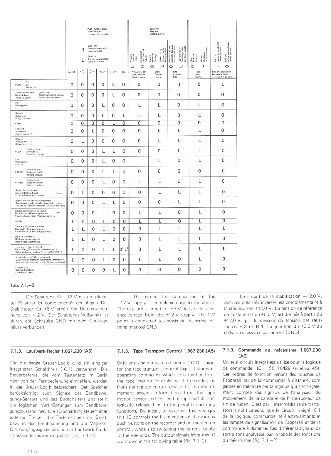
7.1.3. Laufwerk-Regler 1.067.230
(A5)
Für die
ganze
Steuer-Logik wird ein einziger
integrierter
Schaltkreis
(lC
'1
)
verwendet. Die
Steuerbefehle,
die vom Tastensatz im
Gerät
oder von
der Fernbedienung eintreffen, werden
in der
Steuer-Loglk
gespeichert.
Der
Speicher
berücksichtigt
auch Signale des
Bandbewe-
gungs-Sensors
und des Endschalters und stellt
die logischen Verknüpfungen zum Bandbewe-
gungszustand
her. Die lC-Schaltung steuert über
externe Treiber die Tastenlampen im Gerä1,
bzw.
in
der
Fernbedienung und
die Magnete.
Die Ausgangssignale
sind in der Laufwerk-Funk-
tionstabel le
zusammengestel lt
{
Fig. 7. 1 .-2).
7.1,3. Tape Transport Control
1.067.230
(A5)
OnlV one single
integrated circuit
(lC
1)
is used
for
the
tape transport
control
logic.
lt stores all
operating
commands
whlch arrive
either
from
the
tape motion
controls
on the
recorder, or
from the
remote control
device.
In addition,
its
memory
accepts
informations
from
the tape
motion sensor
and
the end-of-tape
switch,
and
logically
relates
them to the
possible
operating
functions.
By means of
external drivers
stages
this lC controls
the
illumination of
the
various
push
bultons
on the
recorder and on
the
remote
control, while
also
switching the
current
supply
to the solenoids.
The output signals
from
this I C
are shown
in the
following table
(flg.
7.1.-2).
7.1.3.
Commande du m6canisme 1.067.230
(A5)
Un seul
circuit int6grd est utilisd
pour
la logique
de
commande: lC 1, SC
'1
0429
(sch6ma
A5).
Les ordres
de
fonction venant
des touches de
l'appareil
ou
de la commande
ä distance, sont
gardds
en mdmoire
par
la logique
qui
tient 6gale-
ment
compte des signaux de l'analyseur du
mouvement
de la bande et de l'interrupteur de
fin
de ruban-
C'est
par
l'intermddiaire de transi-
stors
amplificateurs,
que
le circuit intdgrd
lC 1
de la logique,
commande les 6lectro-aimants et
les lampes
de signalisation de l'appareil et de
la
commande
ä distance. Ces diff6rents signaux
de
sortie sont
analysdes
par
la
tabelle
des fonctions
du mdcanisme
\1i9.7.1
.-2).
7.1 .3
 Loading...