TAPE
TE\SION
S'NSOF
Fis.7.1.-3
I
t/
Fig.
7 .1.-4
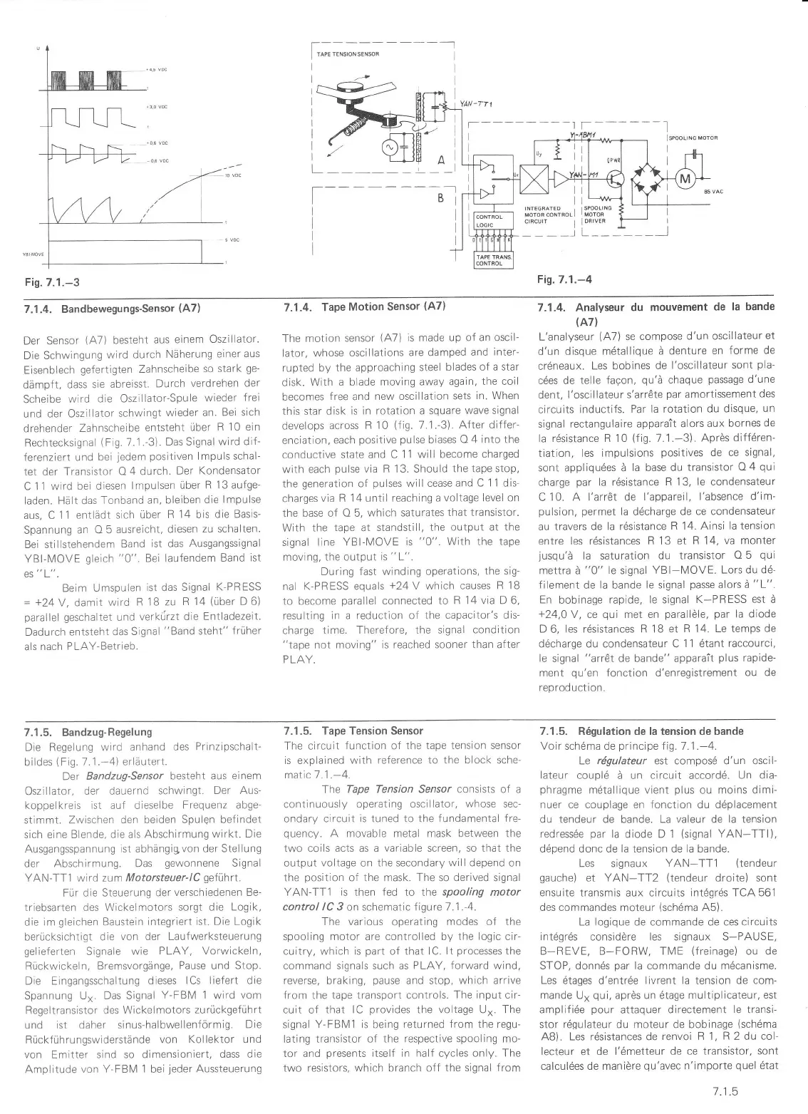
7.1.4. Bandbewegungs-Sensor {47)
Der Sensor
(,A7)
besteht
aus
einem
Oszlllator.
Die Schwingung
wtrd
durch
Näherung
einer aus
Eisenblech
gefertigten Zahnscheibe
so stark
ge-
dämpft,
dass sie
abreisst.
Durch
verdrehen
der
Scheibe
wird
die Oszlllator-Spule
wieder
frei
und
der Oszillator
schwingt
wieder an.
Bei sich
drehender
Zahnscheibe
entsteht
über R
10 ein
Rechtecksignal
(Fig.
7.1.-3).
Das Signal
wird dit
ferenziert und
bei
jedem
positiven
lmpuls schal-
tet der
Transistor
O 4 durch.
Der
Kondensator
C 11 wird
bei dlesen
lmpulsen
über
R 13 aufge-
laden. Hält das
Tonband
an. bleiben
die
lmpulse
aus, C
11 entlädt sich
über
R 14 bis die
Basis-
Spannung
an O 5
ausreicht,
diesen
zu schalten.
Bel stillstehendem
Band
lst das Ausgangssignal
YBI-MOVE
gleich
"0".
Bei laufendem
Band
ist
ESL
Beim
Umspulen
ist das
Slgnal
K-PRESS
=
+24Y,
damit
wird R
18 zu
R 14
(über
D 6)
pa'a'lel gescl'alteL
und
verkürzt
d:e Enlladezeit.
Dadurch
entsteht das
Signal
"Band
steht"
früher
als nach PLAY-Betrieb.
7.1.4.
Tape
Motion
Sensor
(A7)
The motion
sensor
(A7)
is made
up of an oscil-
lator, whose
oscillations
are damped
and
inler-
rupted by
the approaching
steel
blades of a star
disk. With
a blade moving
away again,
the coil
becomes
free
and
new oscillation
sets
in. When
this star
disk
is in rotation a square
wave signal
develops across
R 10
(fig.
7.1.-3).
After differ-
enciation,
each
positive pulse
biases
O 4 inlo the
conductive
state änd C
11 will become charged
with each
pulse
via R 13. Should
the tape stop,
the
qeneration
of
pulses
will
cease and
C 11 dis-
chargesvia
R
14
until
reaching avoltage
level on
the base of O 5, which
saturates
that transistor.
With
the
tape
at
standstill,
the output at the
signal
line YBI-[/IOVE
is
"0".
With the
tape
moving,
the output
is
"L".
During fast winding
operations,
the sig-
nal K-PRESS equals
+24V
which
causes R 1B
to
become
parallel
connected to
F 14 via D 6,
resulting
in
a
reduction of the
capacitor's dis-
charge time-
Therefore, the signai
condition
"tape
not moving"
is reached sooner
than
after
PLAY.
7.1.4. Analyseur
du mouvement
de la bande
(A7)
L'analyseur
(,A7)
se
compose
d'un oscillateur
et
d'un disque
m6tallique ä
denture
en
forme de
crdneaux.
Les bobines
de
l'oscillateur
sont
pla-
c6es de telle
faqon,
qu'ä
chaque
passage
d'une
dent, l'oscillateur
s'arr6te
par
amortissement
des
circuits
inductifs.
Par la rotation
du disque,
un
signal rectangulaire
apparait alors aux
bornes
de
la rdsistance
R 10
(fig.
71.-3).
Aprös diffÖren-
tiation, les impulsions
positives
de ce signal,
sont appliqu6es ä
la base du
transistor
O4
qui
charge
par
la rdsistance
R 13, le condensateur
C
'1
0. A l'arrÖt de
l'appareil, l'absence
d'im-
pulsion, permet
la d6charge
de ce condensateur
au travers
de la r6sistance
R 14- Ainsi
la tension
entre les rdsistances
R 13 et R 14,
va monter
jusqu'ä
la saturation du
transistor
O 5
qui
mettra ä
"0"
le signal
YBI-[/OVE.
Lors du d6-
filement
de
la
bande
le signal
passe
alors
ä
"L".
En
bobinage
rapide, le signal
K-PRESS est ä
+24,0V,
ce
qui
met en
parallöle, par
la diode
D
6,
les rdsistances R 18 et
R 14. Le temps
de
d6charge du condensateur C
1 1 6tant
raccourci,
le
signal
"arr6t
de bande"
apparait
plus
rapide-
ment
qu'en
fonction d'enregistrernent
ou de
reprod uction.
7.1.5. Bandzug-Regelung
Die Regelung
wird anhand
des
Prinzipschalt-
bildes
(Fig.
7.1.-4)
erläutert.
Der
Bandzug-Sersor
besteht aus einem
Oszillator,
der dauernd
schwingt.
Der Aus-
koppelkreis ist auf dieselbe
Frequenz abge
stimmt. Zwischen den
beiden Spulgn befindet
sich
eine Blende, die als
Abschirmung wirkt.
Die
Ausgangsspannung
ist abhängigvon
der Stellung
der
Abschirmung. Das
gewonnene
Signal
YAN-TT1
wird
zum Motorsteuer-lC
geführt.
Für die
Steuerung der
verschiedenen Be-
triebsarten des Wickelmotors
sorgt die Logik,
die im
gleichen
Baustein
integriert
ist. Die Logik
berücksichtigt die
von der Laufwerksteuerung
gelieferten
Signale
wie
PLAY, Vorwickeln,
Rückwickeln, Bremsvorgänge,
Pause
und Stop.
Die Eingangsschaltung
dieses
lCs liefert die
Spannung
U". Das Signal
Y-FBM
1
wird
vom
Regeltransistor des Wickelmotors
zurückgeführt
und
ist daher sinus-halbwellenförmig.
Die
Rückführungswiderstände
von Kollektor und
von Emitter sind so dimensioniert,
dass die
Amplitude
von Y-FBM 1 bei
jeder
Aussteuerung
7.1.5. Tape Tension Sensor
The circuiL
lunction
of
the
tape tension sensor
is explained
with reference to the
block
sche-
malic-7.1 .-4.
The
Tape Tension Sensor consists of a
continuously operating
oscillalor,
whose
sec-
ondary circuit is tuned to the
fundamental fre-
quency.
A movable metal mask
between
the
two
coils acts
as a
variable screen, so that the
output
voltage on the secondary will depend on
the
position
of the mask. The so derived signal
YAN-TT1
is
then
fed
rc rhe
spooling
motor
control /C 3 on schematic f igure 7.'1 .-4.
The various
operat;ng
modes of the
spooling motor
are
controlled by the logic cir
cuitry, which is
part
of that lC.
lt
processes
the
command signals such as
PLAY, forward
wind,
reverse, braking,
pause
and stop, which arrive
from
the tape transport controls.
The input cir
cuit of
that lC
provides
the
voltage
U". The
signal Y-FBM1 is being
returned from the regu-
lating
transistor of the respective spooling mo-
tor and
presents
itself in
half cycles
only. The
two
resistors, which branch off the
signal from
7.1:5. R6gulation de la tension de bande
Voir sch6ma de
principe
Iig.7.1 .-4.
Le rögulateur est compos6 d'un oscil-
lateur couplö
ä un
circuit
accord6.
Un dia-
phragme
mdtallique vient
plus
ou moins dimi-
nuer ce couplage en fonction du ddplacement
du tendeur de bande. La
valeur
de
la
tension
redressde
par
la diode D 1
(signal
YAN-TTI),
ddpend donc de la tension de la bande.
Les signaux
YAN-TT1
(tendeur
gauche)
et YAN-TT2
(tendeur
droite) sont
ensuite
transmis aux
circuits int6gr6s TCA 561
des commandes moteur
(sch6ma
,A5).
La logique de commande de ces circuits
int6gr6s
considöre les signaux S-PAUSE,
B-REVE, B-FORW, TME
(freinage)
ou de
STOP, donn6s
par
la commande du mdcanisme.
Les
ötages d'entrde livrent
la
tension
de com-
mande
U"
qui,
aprös un 6tage multiplicateur,
est
amplifi6e
pour
attaquer
directement
le
transi-
stor rdqulateur du moteur de bobinage
(schöma
AB). Les rösistances de
renvoi R 1,
R
2 du col-
lecteur
et
de l'6metteur
de ce transistor,
sont
calcul6es
de maniöre
qu'avec
n'importe
quel
6tal
I t.5
 Loading...