D21m System
Introduction 2-1Date printed: 11.07.07
2 INTRODUCTION
The D21m I/O system provides very cost-effective inputs and outputs with
maximum fl exibility while maintaining the well-known Studer sound quality.
It is the fi rst Studer I/O system providing full 96 kHz operation. Different
I/O modules can be plugged into a frame, providing I/O systems tailor-made
to customer needs. And all this comes with an unequalled form factor. Full
redundancy is available starting from power supplies going up to redundant
interconnections and DSP cards.
Note: The examples in this document use the SCore. Although most applications
refer to this usage, the majority is also valid for use with the Performa core.
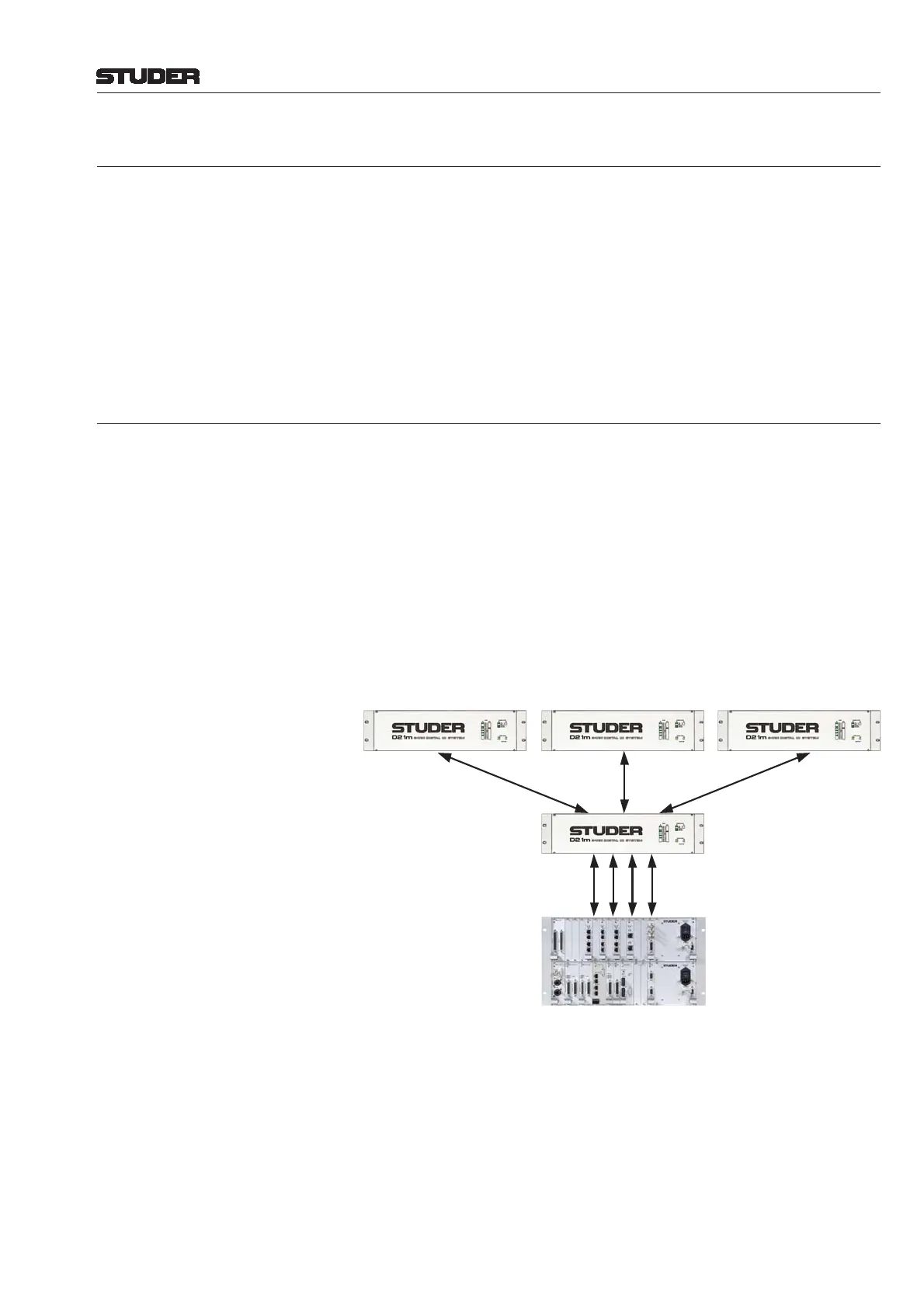
2.1 System Philosophy
When using the D21m I/O system the DSP core itself does not provide I/O,
but is connected to the fi rst D21m frame within the system (acting as a hub)
by using Studer proprietary “HD Link” technology. On the DSP core side,
the connection is made to the DSP card(s) directly. Link distance is limited
to 10 m, so the fi rst I/O box should be located close to the DSP core. From
that frame it is possible to run optical-fi ber MADI links to multiple places,
up to several kilometers away. By using this “star” architecture it is ensured
that a possible problem with one of the remote I/O boxes will not lead to a
general breakdown of the whole I/O system. A maximum of six remote I/O
boxes (stage boxes) may be connected to one hub frame. Should more I/O
channels be required then multiples of the “local frames” (hubs) may be used
within the system.
Redundancy issues are regarded as highly important. It is therefore possible
to run any MADI links with redundant cables. The system is automatically
switching to the redundant connection in case the primary connection should
fail. For 96 kHz operation the second link can be used as a channel count
extension, transferring a total of 64 MADI channels even at 96 kHz sampling
frequency. The “redundant” MADI link may also be used for sharing an I/O
box between two consoles.
The MADI link between the fi rst D21m frame (hub) and the remote I/O boxes,
in addition, carries all control signals needed to control the microphone ampli-
fi er cards, to interrogate the state (health) of any remote I/O card and to dis-
play it within the console’s system surveyor page. This is without sacrifi cing
SCore &
I/O Frame
D21m Hub & IO
D21m Remote IO D21m Remote IO D21m Remote IO
MADI
MADI
MADI
RS422 Link to Desk
Studer Proprietary HD Link