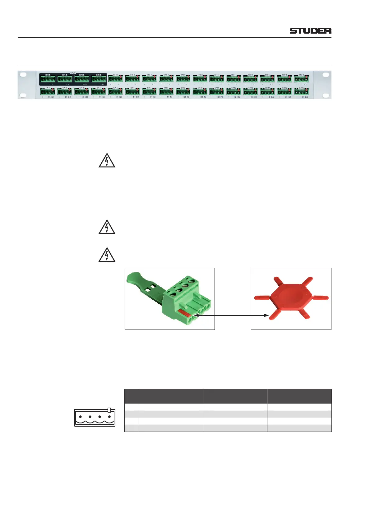
6.7.5.3 GPIO Break-Out Box 1.949.588
For easier wiring of single GPI and/or GPO signals, this break-out box can
be used. 16 GPI signals and 12 of the 16 GPO signals of a GPIO card with
relay outputs (1.949.436) are wired to single, 4-pin Combicon terminals (see
below), providing the relay contacts or opto-coupler inputs, as well as GND
and a short circuit-proof 5 V
DC
supply.
If voltages exceeding 50 V (AC or DC) are switched, the break-out box must
be placed within a closed rack in order to avoid shock hazards by touching
the contacts!
Four of the 16 GPO signals (GPO 1...4, marked in black on the front panel) are
connected to solid-state relays whose power terminals are wired to the Com-
bicon terminals. These power contacts can switch AC loads from 24...240 V
with a maximum total current of 5 A over all 4 relays.
For safety reasons, these four terminals have no additional GND and 5 V
supply. All remaining low-voltage terminals (GPI 1...16, GPO 5...16) are
coded on pin #4 in order to prevent high-voltage connectors being inserted
by mistake.
The high-voltage connectors must be coded, as shown below; six coding
elements (order no. 54.25.1100) are included with the break-out box.
Eight 4-pin Combicon connectors with screw terminals (54.25.1104) are
included with the break-out box. If more connectors are required, please
order separately. On the rear of the box two 37-pin D-type sockets (f) are
provided for connection to the GPIO card. For matching cables please
refer
to chapter 6.7.6.
Pin Assignment:
Pin
GPO 1...4 (Outputs)
(upper row, *coded)
GPO 5...16 (Outputs)
(opper row, uncoded)
GPI 1...16 (Inputs)
(lower row, uncoded)
1 n.c. +5 V +5 V
2 n.c. GND GND
3 Power Relay, Contact 1 GPO Relay, Contact 1 Optocoupler Input 1
4 Power Relay, Contact 2 GPO Relay, Contact 2 Optocoupler Input 2
Socket View
1234
*
Coding Element
D21m System
6-60 D21m Modules Date printed: 30.08.07