D21m System
D21m Modules 6-41Date printed: 25.09.07
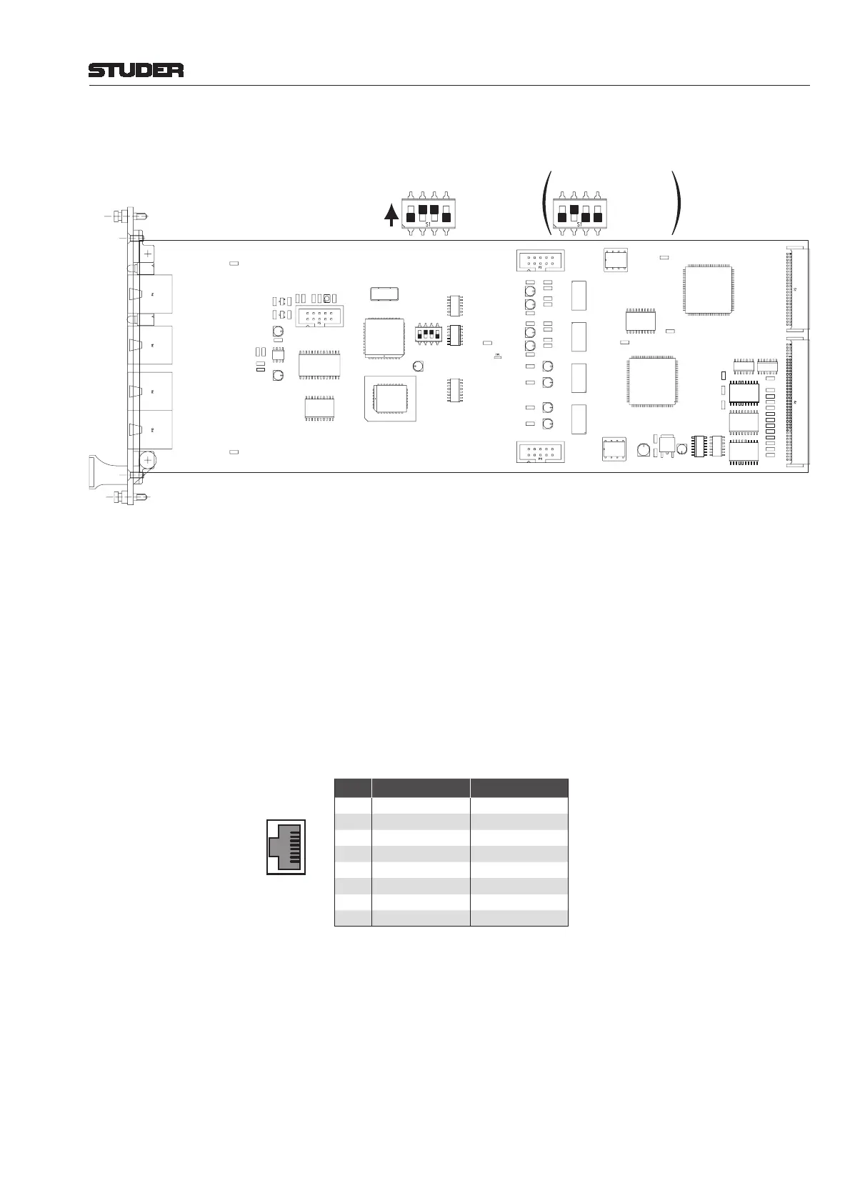
LEDs: On if a valid signal is available at the input that is locked to the system
clock.
DIP switch: When using the Performa core, only 48 channels can be transmitted from the
core to the D21m system. In order not to lose audio data, the channel selector
of the HD card S has to be confi gured to this mode by setting switch #1 of
DIP switch S1 to the ON position.
The other three switches #2...4 have to remain in their default positions and
must not be changed.
Note: The default settings for the card versions 1.949.412.21 and 1.949.412.22 are
different, as shown in the diagram above.
Connector Pin Assignment: (8-pin RJ45)
Pin Signal (Input) Signal (Output)
1 Rx 0 + Tx 0 +
2 Rx 0 – Tx 0 –
3 Rx 1 + Tx 1 +
4 Rx Clk + Tx Clk +
5 Rx Clk – Tx Clk –
6 Rx 1 – Tx 1 –
7 Rx 2 + Tx 2 +
8 Rx 2 – Tx 2 –
Performa Mode
Don't change
Don't change
For Future Use
S1
4321
Default setting
for 1.949.412.21
Default setting
for 1.949.412.22
Performa Mode
Don't change
Don't change
For Future Use
ON
1
8
Socket View