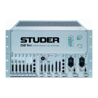
D21m System
D21m Modules 6-51Date printed: 03.11.07
DIP Switch: S2 DIP switch for master port selection (versions 1.949.438.22 and up):
1 2 3 4 Setting
OFF
Depending on application (factory default):
– SCore: Master port connected to bridge/host card
– D21m stand-alone mode: Master port connected to front-panel
MASTER socket
ON Master port forced to front-panel MASTER socket (Vista 5 only)
OFF OFF OFF reserved - NO OTHER SETTINGS ALLOWED!
Connector Pin Assignment: RS422 MASTER (9-pin D-type, female)
Pin RS422 Controller RS422 Device
1
Chassis Chassis
2
RxD – TxD –
3
TxD + RxD +
4
GND GND
5
n.c. n.c.
6
GND GND
7
RxD + TxD +
8
TxD – RxD –
9
Chassis Chassis
Note: The RS422 SLAVE connector (P2) is always wired in controller mode.
S2
ON
Default Setting:
3214
1
5
9
6
Solder/Crimp View
(or Socket View)

 Loading...