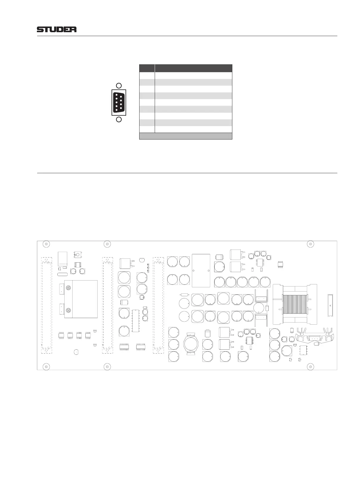
STATUS (9-pin D-type, female) on earlier version 1.949.403:
Pin Signal
1 * Relay NO (normally open)
2 * Relay COMMON
3 Relay NC (normally closed)
4 n.c.
5 n.c.
6 +24 V
DC
(650 mA max.)
7 n.c.
8 GND
9 GND
* Connected if everything is ok
6.7.2 LED/PSII PCB 1.949.402
The primary power supply unit(s) as well as the frame’s backplane PCB are
directly plugged to the PSII PCB. It generates all the DC voltages required by
the frame from the 24 V
DC
delivered by the primary power supply unit(s), and
it constantly monitors all supply voltages. As long as everything is ok, a relay
is energized. In case of failure of any one of the supply voltages, the relay
releases. Both NO and NC relay contacts are available on the FAN/STATUS
front panel connector of the right-hand primary PSU only.
The PSII PCB contains no adjustable elements.
The LED part of the PCB (not shown here) is located behind the frame’s front
panel and connected with a ribbon cable to P1 of the PSII PCB; it indicates
available/missing cards and supply voltages as well as the boot sequence and
errors while booting.
1
5
9
6
Solder/Crimp View
(or Socket View)
D21m System
D21m Modules 6-57Date printed: 30.08.07